background image

5

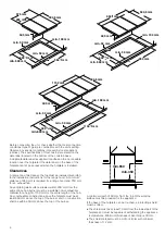
The shield overall dimensions must be 560 mm wide x 

480 mm deep.

Provide cut-out in right hand rear of shield of 80 mm wide x 

80 mm deep to provide for gas regulator / LP connection 

fitting.

After installation of the shield the clearance around the top and 

sides of shield will allow adequate ventilation. Ensure the side 

and top clearances are not obstructed.
If an oven is positioned below the cooktop the barrier does not 

need to be fitted, but a space of 35 mm must be maintained 

between the underside of the cooktop and the top of the oven.

Installation of cooktop into the kitchen bench

Side clearances: If the distance measured from the periphery of 

the nearest burner to any vertical surface is less than 200 mm, 

the surface shall be protected in accordance with clauses 

6.10.1.2 of AS/NZS 5601.1.
For cutout dimensions and clearances see 

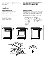
Preparing to install

.

Installation procedure:
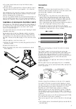
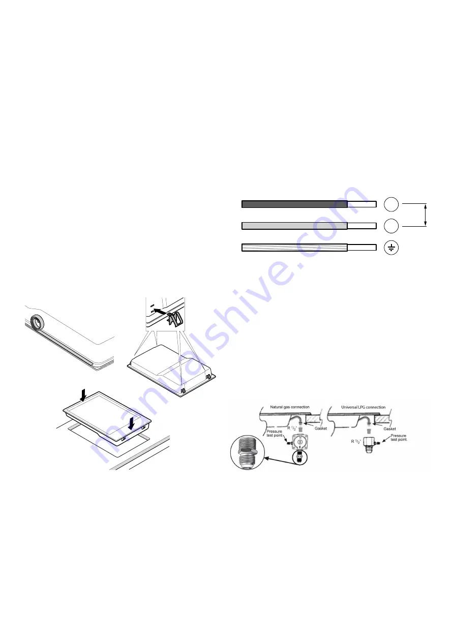
Depending on the model, the adhesive seal may be factory-

fitted. If this is the case, it should not be removed under any 

circumstances, since the adhesive seal prevents leaks. If the 

seal has not been factory-fitted, apply it to the underside of the 

hob.
Fitting the appliance onto the kitchen unit:

1.

Remove the clips from the accessory bag and place them in 

the lateral orifices. 

2.

Insert and centre the hob.

3.

Press the sides of the hob until it is supported around its 

entire perimeter.

Connection

Electrical

An electrical 10 amp socket needs to be within 1 m of the 

hotplate to allow electrical connection. The socket must remain 

accessible after installation of the appliance.
Important notes:

This appliance is connected to the mains (240 VAC) by 

means of the connecting lead which must be fixed to the 

kitchen unit to prevent it from coming into contact with hot 

parts of the cooktop (or an oven installed underneath) and 

remain accessible after installation of the cooktop.
When making this connection make sure that the lead cannot 

come into contact with hot parts of the cooktop.

This appliance must be earthed. When connecting the 

cooktop ensure that the earth wire is connected first and that 

all wires are connected to the correct terminals.

Gas

During the planning stage, consider the position of supply 

connections.
The cooktop must be connected to the gas supply with 

upstream connection of an isolation valve in accordance with 

the respectively valid regulations. We recommend that the 

isolation valve be fitted prior to the cooktop to enable isolation 

of cooktop from gas supply. The valve must be easily 

accessible at all times.
To find out the factory set gas type, see bottom of cooktop next 

to gas connection.
Remove plastic cap from gas supply line prior to installation.
Fit regulator (N.G.) or a test point (Universal LPG) directly to the 

R 1/2’’ connection.

Direction of gas flow is indicated on the rear of the regulator.
For position of the inlet connection refer 

Preparing to install

:

Use pipe compound or thread sealant, properly theaded pipes 

and careful assembly procedure so that there is no cross 

threading, etc., which might cause damage or leakage.
Make sure that all connections peformed are free of leakage. 

The manufacturer does not accept any liability for leakage on 

connections performed by the installer or if the L-tube is moved 

or twisted.
Set the burner pressure to 1.0 kPa for natural gas and 2.75 kPa 

for U-LPG with the rapid burner operating.
There are two ways to carry out the connection to the main gas 

line:

The hotplate can be connected with rigid pipe as specified in 

AS/NZS 5601.1

/

9

9

1

99 a

Summary of Contents for PCD345DA

Page 1: ...USER INSTRUCTIONS INSTALLATION INSTRUCTIONS MAINTENANCE INSTRUCTIONS This cooktop is for use with Natural Gas and Universal LPG Leave this instructions with the owner PCD345DA ...

Page 2: ...entilation Do not obstruct the flow of combustion and ventilation air Cabinets installed above the gas cooktop must have a minimum clearance of 650 mm 24 The gas pressure regulator supplied with the appliance must be installed in line with the gas pipe N G only For pressure testing in excess of 3 5 kPa 1 2 psig the appliance and its individual shutoff valve must be disconnected from the gas supply...

Page 3: ...n instructions Local Gas Fitting Regulations Municipal Building Codes Refer to AS NZS 5601 1 for Gas Installations S A A Wiring Code Local Electrical Regulations Any other statutory regulations Preparing to install Refer to AS NZS 5601 1 for piping size details These built in cooktops are intended to be inserted in a benchtop cutout Only an officially authorised technician should connect the appli...

Page 4: ...joining wall surface situated within 200 mm from the edge of any hob burner must be a suitable non combustible material for a height of 150 mm for the entire length of the hob Any combustible construction above the hotplate must be at least 650 mm above the top of the burner and no construction shall be within 450 mm above the top of the burner A minimum depth of 50 mm from the top of the worktop ...

Page 5: ...ing lead which must be fixed to the kitchen unit to prevent it from coming into contact with hot parts of the cooktop or an oven installed underneath and remain accessible after installation of the cooktop When making this connection make sure that the lead cannot come into contact with hot parts of the cooktop This appliance must be earthed When connecting the cooktop ensure that the earth wire i...

Page 6: ...and must comply with current regulations and the conditions laid down by the local gas company Request change over injectors from our customer service deparment refer injector chart below for sizes Before conversion the cooktop must be disconnected from the electricity and gas valves must be turned to the OFF position Changing the nozzles of the burners on the cooktop 1 Remove the pan supports bur...

Page 7: ...parks are produced on all burners The flame ignites 2 Release the control knob 3 Turn the control knob to the required setting If it does not come on turn the control knob to the off setting and repeat the steps above This time press and hold the control knob for longer up to 10 seconds Risk of deflagration If after 15 seconds the flame does not ignite switch off the burner and open a nearby windo...

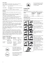
Page 8: ...ns The chart below gives the correct pan usage for each burner Precautions for use The following advice is intended to help you save energy and prevent pan damage Setting Û Control off Large flame Maximum capacity or aperture and elec tricity on Economy flame Minimum capacity or aperture Burner Very high High Medium Low Rapid burner Escalopes steaks ome lettes frying Rice white sauce ragout Steami...

Page 9: ...d Before calling the Technical Assistance Service bear in mind the following advice Any of the following are considered to be abnormal operation and may require servicing Yellow tipping of the cooktop burner flame Sooting up of cooking utensils Burners not lighting properly Gas valves which are difficult to turn in case the appliance fails to operate correctly contact the authorised service provid...

Page 10: ...10 Wiring diagram A Switch B Blue wire C Brown wire D Terminal E Ignition module ...

Page 11: ...B 9000941667 9000941667 Robert Bosch Hausgeräte GmbH Carl Wery Straße 34 81739 München Germany www bosch home com ...

Reviews: