background image


58300000129491_en_a.doc – 04.04.08 

Seite 18 von 24 

6.3 

Replacing motor and belt 

Tools: 


Screwdriver Torx T20 

6.3.1 Procedure 


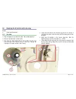
Open the appliance as described under “General disassembly” 


Remove the motor transmission unit from the rubber bushing 


From the underside of the motor transmission unit, unscrew the 4 
Torx T20 screws

 (1)


Push the motor to the centre of the transmission and remove the 
belt from the motor shaft 


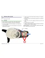
Take the motor from the holder frame and replace it. If necessary, 
insert new belt 


Insert the new motor in the holder frame and slide it in the direction 
of the arrow 


Screw in the 4 Torx T20 screws 

(1)

 until the motor can be slid 

further 


Place the belt on the motor shaft 


Tighten the belt by pulling the motor in the direction of the arrow 
and secure the motor with the screws 

(1)


Check belt tension:

 It must not be possible to push the belt in further 

than 

7 - 10 mm

 from the position shown 


 = 7 – 10 mm 

Summary of Contents for MUM6N1 series

Page 1: ...s 4 3 2 Working with the bowl and the tools 5 3 3 Working with the blender 7 3 4 Cleaning 9 4 COMPONENTS 11 5 FUNCTIONS 12 5 1 Wiring and connecting diagram 12 5 2 Safety systems 13 6 REPAIR 15 6 1 General disassembly 15 6 2 Replacing the lid switch and the housing 17 6 3 Replacing motor and belt 18 7 FAULT DIAGNOSTICS 19 8 TECHNICAL SPECIFICATIONS 20 8 1 Rating plate 20 8 2 Power 21 8 3 Dimension...

Page 2: ... modules can be live Before commencing repairs ALWAYS disconnect the appliance from the power supply If tests have to be conducted while the appliance is live ALWAYS use a residual current operated circuit breaker The protective conductor connection must not exceed the standardised values This is essential for personal safety and appliance function When repairs are complete conduct a test in accor...

Page 3: ...nit in water or clean under running water Do not change accessories and tools until the appliance is at a standstill rotary switch to 0 off 2 2 Scope of delivery The product package varies depending on the appliance model All models contain Twin beating whisk with plastic support Blender jug 1 5 l Protective cover for blender drive Dough scraper Operating instructions 2 2 1 MUM6N1 800 watt motor S...

Page 4: ...evider 3 1 2 Selecting the setting The appliance operates with 4 different speed setting selected with the rotary switch Speed setting M is for momentary operation The drive only runs for as long as the rotary switch is held in position M Level Blender drive r p m Bowl drive r p m 1 5 400 6 200 84 96 2 6 900 8 400 106 128 3 9 500 11 700 146 176 4 13 400 15 800 206 236 M 13 400 15 800 206 236 Rotar...

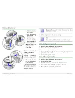
Page 5: ... bowl only if the protective cover is placed on the blender drive If using the blender drive place the protective cover on the unused drive for the bowl Pull the mains cable out of the storage compartment on the rear of the appliance If the mixing bowl is to be used place the protective cover on the blender drive Attach the mixing bowl and turn it anticlockwise to the limit stop Note Failure to ma...

Page 6: ... switch to the desired setting o off Stop Off M Pulse switch Hold rotary switch The drive operates at maximum speed 1 4 Operating speed Set rotary switch to o off to add ingredients 3 2 1 After using the appliance Switch off the appliance with the rotary switch Pull out the mains plug Remove lid and lid rim by rotating them in a clockwise direction Take the tool out of the bowl Remove the bowl by ...

Page 7: ...s a maximum of 0 5 litres 18 fluid ounces of hot or frothing liquid at a time WARNING CAUTION Possible damage to blender Do not put deep frozen fruit and vegetables into the blender Never operate the blender empty Blender will not work unless the cover has been attached and locked 3 3 1 Working with the blender Pull the mains cable out of the storage compartment on the rear of the appliance Remove...

Page 8: ...er handle as far as the limit stop Blender will not work unless the cover has been attached and locked Set the rotary switch to the desired setting Note When working hold the blender cover by the edge 3 3 2 Adding more ingredients Switch off the appliance with the rotary switch Remove the cover and add ingredients or Take out the funnel on the blender cover and gradually add solid ingredients via ...

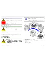
Page 9: ...r with a soft damp cloth If required use a little washing up liquid Then dry the base unit 3 4 2 Cleaning the bowl WARNING Risk of damage Do not wedge plastic parts in the dishwasher as they could be permanently deformed during the washing process Bowl and double whisk are dishwasher proof Do not clean drive shaft of the bowl and kneading hook in the dishwasher Before cleaning the bowl in the dish...

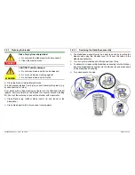
Page 10: ...d into the attached blender approx half full Switch on the blender for several seconds setting M Pour out the water and rinse out the blender with clear water Clean blender jug without blade insert lid and funnel in the dishwasher Clean blade insert with a brush under running water 3 4 3 1 Removing the blade base assembly The blade base assembly may be easily removed by inverting the blender and u...

Page 11: ...58300000129491_en_a doc 04 04 08 Seite 11 von 24 4 COMPONENTS ...

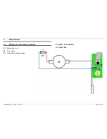
Page 12: ...58300000129491_en_a doc 04 04 08 Seite 12 von 24 5 FUNCTIONS 5 1 Wiring and connecting diagram E1 Electronics p c b M Drive motor S1 Lid switch for blender drive EU 220V 240V 50 60Hz UC 120V 60Hz ...

Page 13: ...otective cover If the blender drive is not needed it is to be covered with the protective cover To use the blender remove the protective cover from the blender drive first To do this press the back of the protective cover and remove the cover 5 2 1 2 Safety lock for blender Attach the blender and rotate all the way in an anti clockwise direction Ensure that the marks on the blender and appliance a...

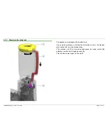
Page 14: ...e is equipped with a safety lock It can only be switched on if either the protective cover or the blender with a locked lid is on the blender drive If the blender lid 1 is turned anticlockwise the slide switch 2 actuates a switch via a tripping device 3 This cuts the power supply to the motor ...

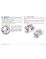
Page 15: ...oup of the appliance to the upper section of the housing To open the housing Lie the appliance on its back Unscrew the 4 crosshead screws 1 in the bottom group Undo the 11 snap in hooks To do so insert a flat tipped slotted screwdriver in the openings on the bottom group and carefully push the snap in hooks in the direction shown in the diagram Detach the upper section of the housing from the bott...

Page 16: ...mage When assembling the appliance you must follow the cable guide 1 Mains cable 2 Electronics module circuit board 3 Blue strand to the lid switch Black strand to the motor 4 The strands must be laid in the recesses on the transmission holder frame motor carrier and upper section of the housing ...

Page 17: ... and electronics circuit board and pull them back through the openings in the upper section of the housing Loosen the screw 3 on the lid switch support do not unscrew it completely and remove the lid switch with the tripping device from the guide Install new lid switches in the reverse sequence Note the tightening torques for the screws 3 0 3 0 6 Nm When assembling the upper section of the housing...

Page 18: ...f the transmission and remove the belt from the motor shaft Take the motor from the holder frame and replace it If necessary insert new belt Insert the new motor in the holder frame and slide it in the direction of the arrow Screw in the 4 Torx T20 screws 1 until the motor can be slid further Place the belt on the motor shaft Tighten the belt by pulling the motor in the direction of the arrow and ...

Page 19: ...58300000129491_en_a doc 04 04 08 Seite 19 von 24 7 FAULT DIAGNOSTICS ...

Page 20: ... C Customer service index Newly launched appliances are given the customer service index 01 The customer service index is increased to 02 03 if parts relevant for customer service are changed in the appliance D Frequency E Production date according to BSH key For example FD8710 87 year minus 20 2007 10 month October F Serial number optional G Power H Type works designation I Field for approbation ...

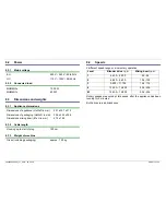
Page 21: ... mm 304 x 440 x 356 Dimensions mixing bowl Ø x H in mm 278 x 196 8 3 2 Cable length Housing up to start of plug 120 cm 8 3 3 Weight of machine Gross including packaging approx 7 50 kg 8 4 Speeds 4 different speed ranges momentary operation Level Blender drive r p m Mixing bowl r p m 1 5 400 6 200 84 96 2 6 900 8 400 106 128 3 9 500 11 700 146 176 4 13 400 15 800 206 236 M 13 400 15 800 206 236 Rot...

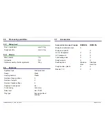
Page 22: ...sing material Plastic Number of drive positions 2 Number of outputs 2 Number of speed settings 4 Capacity of mixing bowl 6 2 l Cord housing Cord store Noise level max 76 dB Plug type Euro plug without earthing 8 7 Accessories Accessories in scope of supply MUM6N2x MUM6N1x Mixing bowl stainless steel X Mixing bowl plastic X Lid rim transparent X X Lid transparent X X Twin beating whisk X X Dough sc...

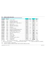
Page 23: ...nism MUZ 6 RG 3 46 0466 Multipurpose mixer transparent Ø 203 mm MUZ 6 RR 2 46 1256 Shredding grating and slicing set Ø 193 mm MUZ 6 TS 5 46 1196 Slicer shredder transparent Ø 203 mm MUZ 6 ZP 1 46 1199 Citrus press MUZ 7 AD 1 46 1200 Adapter for MUM 7 MUZ 7 DS 1 46 1231 Continuous shredder MUZ 7 EB 1 46 1232 Ice cream maker MUZ 7 ER 1 46 1233 Stainless steel mixing bowl Ø 280 mm MUZ 7 FV 1 46 1191 ...

Page 24: ...less steel MUZ 7 MS 1 46 1253 4 wing blade stainless steel MUZ 7 MX 1 46 1201 Polycarbonate blender jug 1 5L socket Ø 140 mm MUZ 7 MX 3 46 1239 Blender jug stainless steel 1 5L socket Ø 140 mm MUZ 7 NV 1 46 1254 Pasta shape attachment MUZ 7 PS 1 08 4890 French fries disc stainless steel Ø 193 mm MUZ 7 RS 1 08 6270 Grater disc coarse stainless steel Ø 193 mm MUZ 7 RV 1 46 1202 Grater attachment MUZ...

Reviews: