Bosch MAP Control Center IUI-MAP0001-2 User Manual Download Page 19

MAP Control Center

Operation | en

19

Bosch Sicherheitssysteme, GmbH

User Manual

2014.11 | 06 | F.01U.168.328

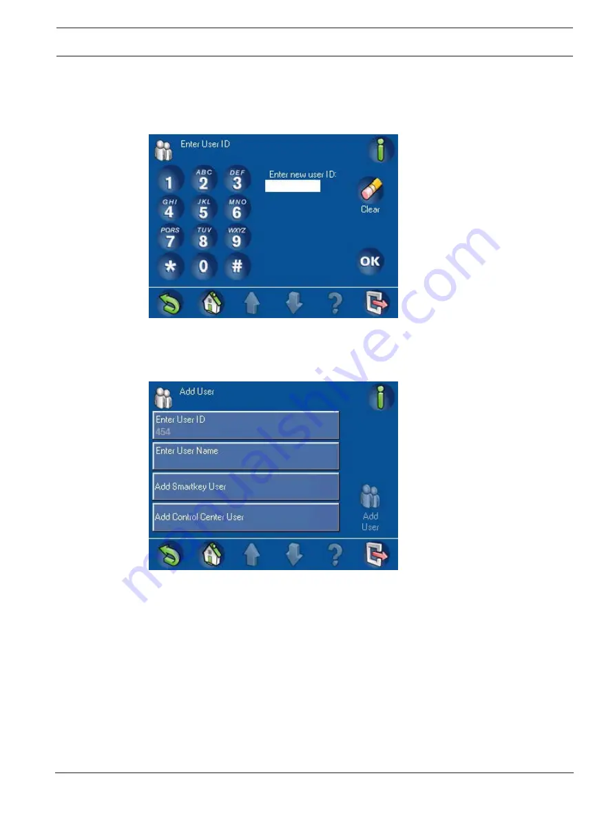
Press the numbered buttons on the keypad screen. Each number appears in the

Enter new user ID

 field. Press 

Clear

 to make corrections.

Press 

OK

 to enter the specific user ID.

Figure 2.15 Enter User ID Keypad screen

The assigned user ID appears in lighter text under the button name on a confirmation
screen (

Figure 2.16 User ID Control Center Confirmation screen, page 19

). Press OK to

complete the entry.

Figure 2.16 User ID Control Center Confirmation screen

Enter User Name

From the 

Add User

 screen (

Figure 2.13 Add User screen, page 18

), press 

Enter User Name

. The 

Enter User Name

 screen (

Figure 2.17 Enter User Name screen, page 20

) opens.

Summary of Contents for MAP Control Center IUI-MAP0001-2

Page 1: ...MAP Control Center IUI MAP0001 2 en User Manual ...

Page 2: ......

Page 3: ...Filtering 11 2 2 1 Search 12 2 2 2 Sort Filter 13 2 3 Arm Using the Control Center 13 2 3 1 Arm All Areas 15 2 3 2 Arm Selected Areas 15 2 3 3 Arm Control Panel Local Area 15 2 4 Disarm Using the Control Center 16 2 4 1 Disarm All Areas 16 2 4 2 Disarm Selected Areas 16 2 4 3 Disarm Control Panel Area 17 2 5 Users 17 2 5 1 Add User 18 2 5 2 Delete User 28 2 5 3 Edit User 29 2 5 4 Change Passcode 3...

Page 4: ...eme GmbH 2 8 8 Change View Output State 57 2 8 9 Manufacturer Authorization 58 2 8 10 Adjust Volume Brightness 59 2 8 11 Chime Mode On Off 59 2 9 Internal Program 60 2 10 Event Memory 61 2 10 1 View Event Memory 61 2 10 2 Clear Event Memory 62 2 10 3 View Alarm Counter 62 2 10 4 Silence 62 2 11 RPS 63 ...

Page 5: ...lor 14 cm 5 7 in LCD screen The durable touch screen provides access to the various system functions through an interface with intuitive buttons Users touch the images directly on the screen to arm disarm or select other menu options The display text is shown in the language set by the user 1 3 1 LCD Screen To operate the MAP control center apply moderate pressure to the keys and buttons shown on ...

Page 6: ... gets inside of the housing To remove fingerprints or dust from the LCD screen use a soft cloth that you have dampened slightly with water 1 5 Idle Screen The control center shows the Idle screen Figure 1 2 Idle screen page 6 when it is not in use To use the system touch the control center display Figure 1 2 Idle screen 1 6 Logging In Use the Login screen Figure 1 3 Login screen page 7 to enter yo...

Page 7: ... Clear the pencil eraser button If an invalid passcode is entered ten1 times in succession the control center is locked for two minutes1 Figure 1 4 Invalid Login screen After the user enters a valid passcode the touch screen shows the Main Menu Figure 1 5 Main Menu screen 1 page 8 See also page 9 1 7 Logging Off A user is logged off By pressing the exit button Table 1 1 Navigation Bar description ...

Page 8: ...onal system information and to clear the events alarms or troubles For more Event Memory information refer to Section View Event Memory page 10 If the Information button is flashing red there are system events and alarms that the user has not cleared If the Information button is flashing yellow there are system troubles which the user has not cleared If the Information button is green no additiona...

Page 9: ...y level After the user presses a button the touch screen shows the task buttons contained within that folder For example Figure 2 45 Status menu page 34 shows the Status tasks Table 1 1 Navigation Bar description Button Description Back Shows the previous screen Home Shows the Main Menu Page up Shows the previous page on screens with more than one page Page down Shows the next page on screens with...

Page 10: ...orded more than one alarm the screen shows the first and last alarms Press View More to see all current events in the event memory For more information about event memory refer to Section View Event Memory page 10 2 1 2 Clear Alarms After silencing an alarm the user must clear the alarm From the alarm screen Figure 2 1 External Intrusion Alarm screen page 10 press View More to open the View Event ...

Page 11: ... 1 Turn on the walk test for the area in which the point is located refer to Section Motion Detector Test page 55 2 Remove the object masking the point and then trigger the point using motion 3 Turn off the walk test again The anti masking message is now cleared 2 2 Searching and Sorting Filtering Some functions in the MAP system user interface call for or require searching sorting or filtering Wh...

Page 12: ...The alphanumeric keypad display has the numerals 0 9 a QWERTY arrangement of letters with additional special characters and five commands refer to Table 2 2 Alphanumeric Keypad Command descriptions page 12 Table 2 2 Alphanumeric Keypad Command descriptions Command Description Shift Creates capital letters Press once The next letter pressed is capitalized Clear Clears all input in the Search field ...

Page 13: ...llation each control center can be assigned to a specific area making that area the local area for that control center Therefore the displayed button name on each control center is unique for each installation Depending on how your system is configured you might need to arm the control panel area first On the Main Menu Figure 1 5 Main Menu screen 1 page 8 press Arm then select an arming option fro...

Page 14: ... 06 F 01U 168 328 User Manual Bosch Sicherheitssysteme GmbH Figure 2 5 Arm menu Notice Clicking on the Not Ready to Arm icon provides information on why the area is not ready to arm Figure 2 6 Exit Delay screen Figure 2 7 Arming Failure screen ...

Page 15: ...armed then press the Arm button Figure 2 8 Arm Selected Areas screen To sort the list of areas before selecting some to arm press the Sort Filter button Refer to Table 2 3 Arming indicators page 15 for the possible arming indicators Table 2 3 Arming indicators Indicator Description Disarmed Area currently disarmed Ready to Arm All points in the area are ready to arm Not Ready to Arm Some points in...

Page 16: ...ol center display shows the message Attention All authorized areas are disarmed Figure 2 10 Attention message All authorized areas are disarmed page 16 Then the Disarm menu opens with the lock button in the unlocked position and the disarmed status showing on the Disarm All Areas button Figure 2 10 Attention message All authorized areas are disarmed 2 4 2 Disarm Selected Areas From the Disarm menu...

Page 17: ...the control panel area press the Control Panel Area button then press the Disarm button The lock icon on the Control Panel Area button changes to the unlocked position and the area s disarmed status shows on the button 2 5 Users Notice The options to perform user related operations are restricted by permission set access profile The Users menu allows the user to add up to the maximum number of use...

Page 18: ... Users menu page 17 press Add User The Add User screen Figure 2 13 Add User screen page 18 opens Figure 2 13 Add User screen Enter User ID From the Add User screen Figure 2 13 Add User screen page 18 press Enter User ID The Enter User ID screen Figure 2 14 Enter User ID screen page 18 opens Figure 2 14 Enter User ID screen Press Enter User ID to enter a specific three digit user ID or press Reques...

Page 19: ... user ID Figure 2 15 Enter User ID Keypad screen The assigned user ID appears in lighter text under the button name on a confirmation screen Figure 2 16 User ID Control Center Confirmation screen page 19 Press OK to complete the entry Figure 2 16 User ID Control Center Confirmation screen Enter User Name From the Add User screen Figure 2 13 Add User screen page 18 press Enter User Name The Enter U...

Page 20: ...c keypad screen 1 page 20 opens Also refer to Figure 2 19 2 Enter User Name Alphanumeric keypad screen 2 page 21 Use the alphanumeric buttons to enter the user s first name Refer to Table 2 3 Arming indicators page 15 for information about using the commands at the bottom of the screen Press Enter to complete the entry The user s first name appears in lighter text under the Enter User First Name b...

Page 21: ...tion about using the commands at the bottom of the screen Press Enter to complete the entry The user s last name appears in lighter text under the Enter User Last Name button name Press Enter to complete the User Name entry Add Smartkey User To designate a Smartkey user press Add Smartkey User on the Add User screen Figure 2 13 Add User screen page 18 The Add Smartkey User screen Figure 2 20 Add S...

Page 22: ...code appears in the Verify Code field Press OK If the token number in the Enter field matches the number entered in the Verify Code field the Smartkey token number appears in lighter text under the Enter Smartkey Token Number button name on the Add Smartkey User screen If these numbers do not match an error message is displayed and you must re enter the token number and verify code Figure 2 21 Ent...

Page 23: ...e Select Smartkey Profile screen to select one of the Smartkey profiles then press OK Figure 2 23 Select Smartkey Profile screen A symbol appears on the Add Smartkey User button Add Control Center User From the Add User screen Figure 2 13 Add User screen page 18 press Add Control Center User The Add Control Center User screen Figure 2 24 Add Control Center User screen page 24 opens ...

Page 24: ...ppears on the button If you press Temporary User a symbol appears on the button and the Temporary User Duration keypad screen Figure 2 26 Temporary User Duration keypad screen page 25 opens Use the screen keypad to enter the number of days 0 to 99 to allow access for the temporary user then press OK to return to the Select User Type screen Notice A temporary user with 0 days validity is an inactiv...

Page 25: ...ontrol Center User screen From the Add Control Center User Figure 2 24 Add Control Center User screen page 24 screen Select User Profile The Select User Profile screen Figure 2 27 Select User Profile screen page 25 opens Figure 2 27 Select User Profile screen From the Select User Profile screen Figure 2 27 Select User Profile screen page 25 select a user profile A symbol appears on the selected bu...

Page 26: ... Figure 2 29 Select User Language page 26 opens From the Select User Language screens 1 or 2 select German English French or Dutch A symbol appears on the selected button Figure 2 29 Select User Language Press the OK button The selected language appears in lighter text under the Select User Language button name From the Add Control Center User screen Select Exit Delay The Select Exit Delay screen ...

Page 27: ... opens Completing Add User When the entries are completed on the Add User screen Figure 2 31 Completed Add User screen page 27 entries in lighter text should appear under the Enter User ID and Enter User Name buttons A symbol should appear on either the Add Smartkey User or Add Control Center User button Notice Until all of the above steps are completed the Add User button will be in lighter text ...

Page 28: ... 33 Delete User screen page 28 opens If necessary press the Search or Sort Filter button to find the user Refer to Section 2 2 Searching and Sorting Filtering page 11 Figure 2 33 Delete User screen From the Delete User screen press one of the menu buttons containing a user s name A message appears asking for confirmation Figure 2 34 Confirm Delete User screen page 29 To proceed press the Confirm D...

Page 29: ...2 5 3 Edit User From the Users menu Figure 2 12 Users menu page 17 press Edit User The Edit User screen Figure 2 35 Edit User screen page 29 opens with a list of users Find the user you wish to edit and press the corresponding button The Edit User User ID screen Figure 2 36 Edit User User ID screen page 30 opens Figure 2 35 Edit User screen ...

Page 30: ...r User ID screen Figure 2 36 Edit User User ID screen page 30 press Edit User Name The Enter User Name screen Figure 2 17 Page 19 opens Press either Enter User First Name or Enter User Last Name The alphanumeric keypad display screen Figure 2 18 Page 20 opens with the name showing in the Enter User Name field Use the editing buttons at the bottom of the screen and the alphanumeric keys to make the...

Page 31: ...n Figure 2 36 Edit User User ID screen page 30 press Edit Control Center User The Edit Control Center User screen Figure 2 38 Edit Control Center User screen page 31 opens Refer to Section Add Control Center User page 23 for instructions on adding or editing information about the control center user Figure 2 38 Edit Control Center User screen 2 5 4 Change Passcode To change a logged in user s pass...

Page 32: ...ules screen page 32 opens with a list of the schedules programmed into the system Figure 2 40 Schedules screen To find a schedule to view or change the user can search or sort the list Press the Search button to show the alphanumeric keypad screen Figure 2 41 1 Search Schedules screen 1 page 32 Use the numeric alphabetic and command keys to enter the name of a schedule The name appears in the Sear...

Page 33: ...orting For more information on searching sorting and filtering refer to Section Searching and Sorting Filtering page 11 Figure 2 43 Sort Filter Schedules screen To view or edit a schedule press the schedule s button The Change Schedule screen Figure 2 44 Change Schedule screen page 34 opens By pressing the schedule s button the user can Disable the schedule or Enable the schedule Figure 2 40 Sched...

Page 34: ...6 Exit Delay screen page 14 is shown The Exit Delay screen indicates how much time you have to exit the area before your presence triggers an alarm 2 7 Status The Status menu provides access to functions for viewing the system status From the Main Menu Figure 1 5 Main Menu screen 1 page 8 press Status then select the status category from the on screen buttons Figure 2 45 Status menu page 34 Figure...

Page 35: ...w Area Status Detail screen Figure 2 47 View Area Status Detail screen page 35 Figure 2 47 View Area Status Detail screen To find an area to view the user can search or sort the list on the View Area Status screen Figure 2 46 View Area Status screen page 35 Press the Search button to show the alphanumeric keypad screen Figure 2 48 1 Search View Area Status screen 1 page 36 Use the numeric alphabet...

Page 36: ...gure 2 50 1 Sort Filter View Area Status screen 1 page 37 see alsoFigure 2 51 2 Sort Filter View Area Status screen 2 page 37 opens Select a filter category from the list List All Areas List Armed Areas List Disarmed Areas List Ready To Arm Areas List Not Ready To Arm Areas List Ready To Disarm Areas List Not Ready To Disarm Areas Press the A Z or Z A button to select the sorting sequence For more...

Page 37: ... 1 Sort Filter View Area Status screen 1 Figure 2 51 2 Sort Filter View Area Status screen 2 See also View Area Status page 36 2 7 2 View Device Status From the Status menu Figure 2 45 Status menu page 34 press View Device Status The Device Status Select screen Figure 2 52 Device Status Select screen page 38 opens ...

Page 38: ...ect Area screen Figure 2 53 Select Area screen page 38 opens Press the button for an area The View Device Status screen Figure 2 54 View Device Status screen page 39 opens with a list of the devices in the selected area Figure 2 53 Select Area screen If All Devices is pressed the View Device Status screen Figure 2 54 View Device Status screen page 39 opens with a list of all devices The device sta...

Page 39: ... 55 Search View Device Status screen 1 page 39 Use the numeric alphabetic and command keys to enter a device s name The name appears in the Search View Device Status field Press the Enter button to start the search Figure 2 55 Search View Device Status screen 1 Figure 2 56 Search View Device Status screen 2 To sort or filter the list of devices press the Sort Filter button The Sort Filter View Dev...

Page 40: ...Devices List Disabled Devices List Enabled Devices Then press the A Z or Z A button to select the sorting sequence For more information on searching sorting and filtering refer to Section Searching and Sorting Filtering page 11 Figure 2 57 Sort Filter View Device Status screen Press one of the device buttons to view additional details of that device A View Device Status Detail screen Figure 2 58 V...

Page 41: ...ce only disables the device s ability to notify the security system of an alarm or trouble event Tamper events are still active in a bypassed device From the Status menu Figure 2 45 Status menu page 34 press Bypass Unbypass Device The Bypass Unbypass Device screen Figure 2 59 Bypass Unbypass Device screen page 41 lists the devices and displays whether each device is either Bypassed or Unbypassed P...

Page 42: ...vices List Unbypassed Devices Then press the A Z or Z A button to select the desired sorting sequence For more information on searching sorting and filtering refer to Section 2 2 Searching and Sorting Filtering page 11 Figure 2 61 Sort Filter Bypass Unbypass Device screen 2 7 4 Unbypass All Devices To unbypass all bypassed devices press Unbypass All Devices on the Status menu Figure 2 45 Status me...

Page 43: ...ce The Service menu provides access to system service functions On the Main Menu Figure 1 5 Main Menu screen 1 page 8 press the Service button The Service menu Figure 2 63 Service Menu screen 1 page 43 Figure 2 64 Service Menu screen 2 page 43 and Figure 2 65 Service Menu screen 3 page 44 opens Figure 2 63 Service Menu screen 1 Figure 2 64 Service Menu screen 2 ...

Page 44: ...2 63 Service Menu screen 1 page 43 press the Event History button The Event History screen Figure 2 66 Event History screen screen 1 page 44 opens Refer also to the Event History screen page 2 Figure 2 67 Event History screen screen 2 page 45 The user can select from View History Print History Filter By Date Range Filter By Event Type Sort By Figure 2 66 Event History screen screen 1 ...

Page 45: ...ng the system system troubles system tampers and so on are listed on the View History screen The default history filter is the last 24 hours To expand the time range select Filter by Date Range refer to Section Filter By Date Range page 46 To view only sensor events refer to Section Event Memory page 61 Figure 2 68 View History screen Print History On the Event History screen Figure 2 66 Event His...

Page 46: ...o change Press the and buttons to change the dates in the range Figure 2 70 Filter Event History Dates screen Filter By Event Type On the Event History screen Figure 2 66 Event History screen screen 1 page 44 press Filter By Event Type The Filter Event History Type screen opens refer to Figure 2 71 Filter Event History Type screen screen 1 page 47andFigure 2 72 Filter Event History Type screen scr...

Page 47: ...ory Type screen screen 1 Figure 2 72 Filter Event History Type screen screen 2 Sort By On the Event History screen Figure 2 67 Event History screen screen 2 page 45 press Sort By The Sort By screen opens showing two options ID Event Type Press one of the options to sort the events The screen returns to the Event History screen with the Sort By choice listed in lighter text on the Sort By button ...

Page 48: ...ersion and the control center s firmware version Figure 2 74 View Version Information screen 2 8 3 Enable Disable Device Disabling a device effectively removes that device from the security system The control panel ignores all signals received from a disabled device Only authorized users such as installers or security officers can disable devices For information on bypassing a device refer to Sect...

Page 49: ...ch Enable Disable Device screen page 49 Use the numeric alphabetic and command keys to enter a device s name The name appears in the Search Enable Disable Device field Press the Enter button to start the search Figure 2 76 Search Enable Disable Device screen To sort or filter the list of devices press the Sort Filter button The Sort Filter Enable Disable Device screen Figure 2 77 Sort Filter Enabl...

Page 50: ... the date or time element to select the value to be modified 2 Press the or button to increase or decrease the element s value 3 Press the OK button when finished The 24 Hour button is inactive It is a reminder that the hours range from 0 midnight through 23 11 p m Figure 2 78 Set Time and Date screen 2 8 5 Walk Test On the Service menu Figure 2 64 Service Menu screen 2 page 43 press Walk Test The...

Page 51: ...propriate authority level Doing so would interrupt the walk test To avoid an interruption of the test the installer can place a note on the control center to indicate that a test is in process From the Walk Test screen press Start New Walk Test The Walk Test Select screen Figure 2 80 Walk Test Select screen page 51 opens showing the following options Select Areas All Points Figure 2 80 Walk Test S...

Page 52: ... 2 82 Sort Filter Select Area screen page 52 opens Select a sorting option from the list List All Areas A Z List All Areas Z A The sorting starts and completes within a few seconds Figure 2 82 Sort Filter Select Area screen For more information on sorting and filtering refer to Section Searching and Sorting Filtering page 11 From the Select Areas screen Figure 2 82 Sort Filter Select Area screen p...

Page 53: ...the View Tested button or the Print Test button When the View Tested button is selected a screen opens with a list of the points already tested The View Tested button is now View Untested This allows the user to toggle between tested and untested points Figure 2 84 Walk Test Points Tested screen The Print Test button is also available on this screen When the Print Test button is selected from the ...

Page 54: ...t Walk Test screen Resume Walk Test The Resume Walk Test button is active only when the user has logged off the control center before all points were tested Refer to Figure 2 86 Walk Test screen all buttons active page 54 Figure 2 86 Walk Test screen all buttons active Start Seismic Test Figure 2 87 Seismic Test screen ...

Page 55: ...ied out if all areas are disarmed Print Walk Test Figure 2 88 Print Walk Test screen See also Walk Test page 54 Walk Test page 55 2 8 6 Motion Detector Test On the Service menu Figure 2 64 Service Menu screen 2 page 43 press Motion Detector Test The Motion Detector Test Select screen Figure 2 89 Motion Detector Test Select screen page 55 appears with a green check mark or a red X symbol on the Mot...

Page 56: ... 91 Motion Detector Test screen Test Mode On If the test mode is On detectors equipped with this function illuminate their LEDs when they sense motion 2 8 7 Bell Test On the Service menu Figure 2 64 Service Menu screen 2 page 43 select Bell Test The Bell Test Progress screen Figure 2 92 Attention Bell Test in Progress page 57 shows that the bell test is in progress During the bell test the control...

Page 57: ...t State screen page 57 opens showing a list of all outputs Output is Off or Output is On Figure 2 93 Change View Output State screen Pressing the output buttons changes the state of the outputs To search the list for a specific output press the Search button The Search Change View Output State screen Figure 2 94 Search Change View Output State screen page 58 opens Use the numeric alphabetic and co...

Page 58: ... Off Outputs List On Outputs Figure 2 95 Sort Filter Change View Output State screen 2 8 9 Manufacturer Authorization From the Service screen Figure 2 65 Service Menu screen 3 page 44 press Manufacturer Authorization The Manufacturer Authorization screen Figure 2 96 Manufacturer Authorization menu page 59 opens The button displays a green check mark or red X mark indicating whether or not the manu...

Page 59: ...he or button to increase or decrease the volume or brightness setting 3 Press one of the button bar buttons to exit from the screen Figure 2 97 Adjust Volume Brightness screen 2 8 11 Chime Mode On Off When Chime Mode is On opening the programmed door a door in the local area the area where the control center is located causes the touch screen to beep once Chime Mode is active only if the system is...

Page 60: ...m Start Stop screen page 60 press a program s on screen button to change the program s state to either Disabled or Enabled Figure 2 99 Internal Program Start Stop screen To sort or filter the list of internal programs press the Sort Filter button The Sort Filter Internal Program Start Stop screen Figure 2 100 Sort Filter Internal Program Start Stop screen page 61 opens Select a filter category fro...

Page 61: ...he following options View Event Memory Clear Event Memory View Alarm Counter Silence Figure 2 101 Event Memory screen To view non sensor events such as arming disarming troubles and tampers refer to Section Event History page 44 See also Screen Elements page 9 2 10 1 View Event Memory This function allows the user to view the system events stored in the control panel since the event memory was las...

Page 62: ...s function allows the user to view the number of system alarms since the control center was installed From the Event Memory screen Figure 2 101 Event Memory screen page 61 press View Alarm Counter The touch screen shows the alarm counter value Figure 2 103 View Alarm Counter screen page 62 Figure 2 103 View Alarm Counter screen 2 10 4 Silence This function allows the user to silence the system buz...

Page 63: ...nection to the control panel On the Main Menu Figure 1 6 Main Menu screen 2 page 9 press the RPS button The RPS screen Figure 2 105 RPS menu page 63 opens showing the following options Authorize RPS Access Cancel RPS Authorization Figure 2 105 RPS menu To allow a remote RPS connection to the control panel press Authorize RPS Access To cancel the authorization for a remote RPS connection to the con...

Page 64: ...Bosch Sicherheitssysteme GmbH Robert Bosch Ring 5 85630 Grasbrunn Germany www boschsecurity com Bosch Sicherheitssysteme GmbH 2014 ...

Reviews: