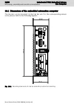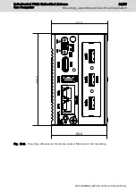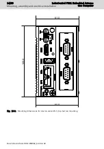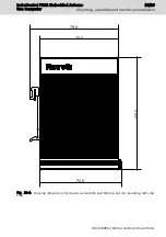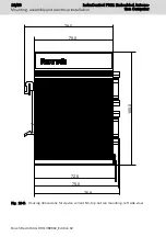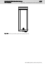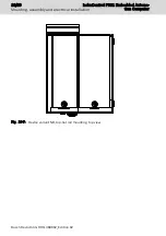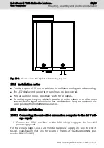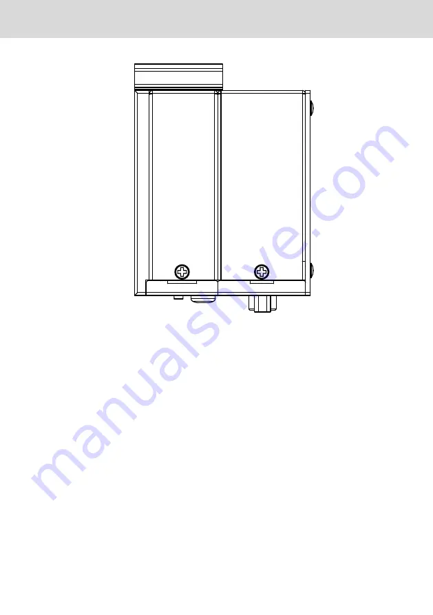
Fig. 10-8: Device variant NC, top-hat rail mounting, top view
10.2 Installation notes
●
Provide a space of 50 mm on all sides for sufficient cooling and cable routing.
●
The LED display on the operator panel must not be covered.
●
Wire all cables in loops. Use strain reliefs for all cables.
●
Do not lay signal carrying cables in parallel to motor cables or to other noise
sources, as the signal transmission can be disturbed. Keep the maximum dis-
tance possible from interference sources.
10.3 Electric installation
10.3.1 Connecting the embedded automation computer to the 24 V volt-
age supply
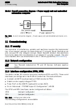
1. Connect the "XD1" interface for the 24 V voltage supply to the industrial
power supply unit.
For the voltage supply, use a 24 V industrial power supply unit acc. to DIN EN
60742, classification VDE 551, for example "VAP01.1H-W23-024-010-NN" (part
number R911171065).
IndraControl PR21 Embedded Automa-
tion Computer
19/29
Mounting, assembly and electrical installation
R911389662_Edition 02 Bosch Rexroth AG
Summary of Contents for IndraControl PR21
Page 1: ...IndraControl PR21 Embedded Automation Computer Operating Instructions R911389662 Edition 02 ...
Page 6: ...IV IndraControl PR21 Embedded Automa tion Computer Bosch Rexroth AG R911389662_Edition 02 ...
Page 32: ...26 29 IndraControl PR21 Embedded Automa tion Computer Bosch Rexroth AG R911389662_Edition 02 ...
Page 35: ...Notes IndraControl PR21 Embedded Automa tion Computer 29 29 ...


