background image

FPE-1000-CITY

en

5

Bosch Security Systems, Inc.

F.01U.078.100 | 04 | 2011.11

Mounting

1.

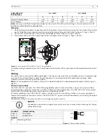
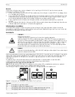
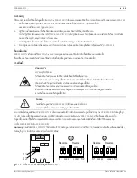
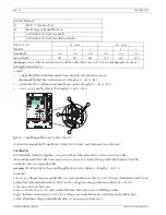
Bring the plug-in module into position with the horizontal terminal lettering facing the front side of the control 
panel. Slide the plug-in module carefully into position along the guide rails (refer to 

Figure 2

Page 5

, Item 1)

2.

Ensure that the connections seat into the slot properly (refer to 

Figure 2

Page 5

, Item 2).

3.

Press down softly until the snap-fit hook locks into place (refer to 

Figure 2

Page 5

, Item 3).

Figure 2

Installing the FPE-1000-CITY City Tie Plug-in Module

To remove a plug-in module, press the snap-fit hook carefully from left to right and pull the board toward the panel 
front.

Wiring

No special wire is required for addressable loops. The wire can be untwisted, unshielded, solid or stranded as long 
as it meets the National Electric Code 760-51 requirements for power-limited fire protective signaling cables.
Observe a maximum circuit resistance of 65

Ω

.

Note:

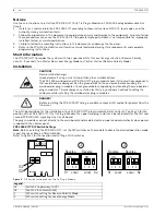
 Use the appropiate DIP switch setting at the module to obtain the desired operation mode (refer to 

Figure 1

Page 4

).

Reverse Polarity Mode

The FPE-1000-CITY connects the FPA-1000 Analog Addressable Fire Panel to either a single set or a pair of dual 
leased telephone company (telco) lines in NFPA 72 Remote Station applications. The FPE-1000-CITY relays system 
alarm status information from the control panel to a monitoring station.
In normal conditions, the FPE-1000-CITY sends a steady current to a monitoring station. In an alarm condition, it 
reverses the polarity of the output current. The FPE-1000-CITY signals a trouble condition by interrupting the output 
voltage and current.
The default setting is fire alarm for circuit 1 and supervisory for circuit 2. 

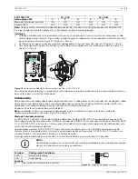
FPE-1000-CITY 
DIP Switches

S1 = SUP

S2 = ALM

1

2

3

1

2

3

Reverse Polarity Mode

ON

ON

ON

ON

ON

ON

Local Energy

OFF

OFF

OFF

OFF

OFF

OFF

Note:

 You may use different operation modes for the circuits. The DIP switch settings 1 to 3 for each switch (S1 

and S2) must be set to the same position.

NOTICE! 

Intended for connection to a polarity reversal circuit of a remote station receiving unit having 
compatible ratings.

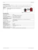
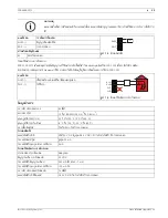
Terminal

Default setting

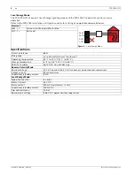
Figure 3

Reverse Polarity Mode

ALM - | +

Fire Alarm

SUP - | +

Supervisory

Legend

M

Monitoring Station

@  

_

.  :  ,

?

A  a

Gas Alarm

Silenced

Power

Trouble

Fire

Supervisory

DRILL

RESET

SILENCE

ACK

2

1

1

3

ALM -+

-

+

SUP

M

Summary of Contents for FPE-1000-CITY

Page 1: ...City Tie Plug in Module FPE 1000 CITY en Installation Guide es Guía de instalación pt Manual de Instalação th คู มือการติดตั ง ...

Page 2: ......

Page 3: ...FPE 1000 CITY 3 Bosch Security Systems Inc F 01U 078 100 04 2011 11 en Installation Guide 4 es Guía de instalación 7 pt Manual de Instalação 10 th คู มือการติดตั ง 13 ...

Page 4: ...lely for the first and second FPE 1000 SLC Signaling Line Circuit board The plug in modules connect directly to the main board and are detected and supervised automatically when power is applied to the control panel FPE 1000 CITY DIP Switch Settings Note Before installing the FPE 1000 CITY set the DIP switches on the module to obtain the desired operation mode Local Energy or Reverse Polarity Mode...

Page 5: ...Page 4 Reverse Polarity Mode The FPE 1000 CITY connects the FPA 1000 Analog Addressable Fire Panel to either a single set or a pair of dual leased telephone company telco lines in NFPA 72 Remote Station applications The FPE 1000 CITY relays system alarm status information from the control panel to a monitoring station In normal conditions the FPE 1000 CITY sends a steady current to a monitoring st...

Page 6: ...d Circuit resistance 65 Ω Wire gauge 12 to 18 AWG 3 3 mm2 to 0 8 mm2 Operating temperature 32 F to 120 F 0 C to 49 C Storage temperature 4 F to 140 F 20 C to 60 C Relative humidity Up to 93 non condensing Reverse Polarity Mode Nominal Voltage 24 V DC nominal 26 4 V DC maximum power limited supervised Output current 33 mA maximum Supervisory standby current 5 mA Local Energy Mode Type of connection...

Page 7: ...n FPE 1000 SLC Los módulos enchufables se conectan directamente a la placa principal y se detectan y supervisan de forma automática cuando el panel de control recibe alimentación Ajustes del conmutador DIP FPE 1000 CITY Nota antes de instalar el dispositivo FPE 1000 CITY configure los conmutadores DIP en el módulo para obtener el modo de funcionamiento deseado energía local o modo de polaridad inv...

Page 8: ...consulte Figura 5 Página 7 Modo de polaridad inversa El módulo FPE 1000 CITY conecta la Central de Incendios Analógica Direccionable FPA 1000 a una o dos líneas telefónicas arrendadas a la compañía telefónica para aplicaciones de Estación Remota NFPA 72 El dispositivo FPE 1000 CITY suministra información del estado de alarma del panel de control a la estación de monitoreo En condiciones normales e...

Page 9: ... circuito 65 Ω Sección del cable De 3 3 mm2 a 0 8 mm2 de 12 a 18 AWG Temperatura de operación De 0 C a 49 C de 32 F a 120 F Temperatura de almacenamiento De 20 C a 60 C de 4 F a 140 F Humedad relativa Hasta 93 sin condensación Modo de polaridad inversa Tensión nominal Nominal de 24 VCC máxima de 26 4 VCC potencia limitada supervisada Corriente de salida 33 mA máximo Corriente de supervisión espera...

Page 10: ...inha de Sinalização FPE 1000 SLC Os módulos plug in são conectados diretamente à placa principal e são detectados e supervisionados automaticamente quando o painel de incêndio é alimentado com corrente elétrica Configurações do interruptor DIP do FPE 1000 CITY Nota Antes de instalar o FPE 1000 CITY configure os interruptores DIP no módulo para selecionar o modo de funcionamento desejado Energia Lo...

Page 11: ...a 9 na Página 10 Modo de Polaridade Invertida O FPE 1000 CITY conecta o Painel de Incêndio Endereçável Analógico FPA 1000 a um conjunto de uma ou duas linhas duplas privativas da companhia telefônica companhia telefônica em aplicações de Estações Remotas NFPA 72 O FPE 1000 CITY retransmite as informações do estado do alarme do sistema do painel de incêndio para uma central de monitoramento de alar...

Page 12: ...uito 65 Ω Bitola do cabo 12 a 18 AWG 3 3 mm2 a 0 8 mm2 Temperatura de operação 0 C a 49 C 32 F a 120 F Temperatura de armazenamento 20 C a 60 C 4 F a 140 F Umidade relativa Até 93 sem condensação Modo de Polaridade Invertida Tensão Nominal 24 Vcc nominal máximo de 26 4 Vcc com limitação de corrente supervisionada Corrente de saída 33 mA no máximo Corrente em supervisão em repouso 5 mA Modo de Ener...

Page 13: ...โมดูลปลั กอิน City Tie FPE 1000 CITY โปรดดูที รูป 14 หน า 14 ช องปลั กอินสองช องด านบนสามารถใช สําหรับบอร ดวงจรสายส งสัญญาณ FPE 1000 SLC ตัวที หนึ งและตัวที สองเท านั น โมดูลปลั กอินเหล านี ติดตั งกับเมนบอร ดได โดยตรงและจะได รับการตรวจจับและควบคุมโดยอัตโนมัติเมื อจ ายไฟฟ าให กับแผงควบคุม การตั งค าสวิตช DIP สําหรับ FPE 1000 CITY หมายเหตุ ก อนติดตั ง FPE 1000 CITY ให ตั งค าสวิตช DIP บนโมดูลตามโหมด...

Page 14: ...ปรดดูที รูป 13 หน า 13 โหมดสลับขั ว FPE 1000 CITY เชื อมต อกับแผงควบคุมอัคคีภัยที สามารถระบุตําแหน งได แบบอะนาล อก FPA 1000 เข ากับคู สายโทรศัพท เช าของบริษัท telco ชุดเดียวหรือสายคู ในแอพพลิเคชันสําหรับสถานีทางไกล NFPA 72 ข อมูลสถานะสัญญาณเตือนของระบบรีเลย FPE 1000 CITY จากแผงควบคุมเข ากับสถานีตรวจสอบ ในสถานการณ ปกติ FPE 1000 CITY จะส งกระแสไฟคงที ไปยังสถานีตรวจสอบ ในสถานการณ ที มีสัญญาณเตือน โมด...

Page 15: ...ถานีตรวจสอบ แผงขั วต อ รูป 16 โหมดใช พลังงานภายในระบบ ALM เชื อมต อกับมาสเตอร บ อกซ ของเขตชุมชน SUP ไม ใช งาน ความต านทานของวงจร 65 Ω ขนาดสายไฟ 12 ถึง 18 AWG 3 3 มม 2 ถึง 0 8 มม 2 อุณหภูมิในการทํางาน 32 F ถึง 120 F 0 C ถึง 49 C อุณหภูมิในการเก บรักษา 4 F ถึง 140 F 20 C ถึง 60 C ความชื นสัมพัทธ ไม เกิน 93 ไม มีการควบแน น โหมดสลับขั ว แรงดันไฟฟ าปกติ ปกติ 24 V DC สูงสุด 26 4 V DC จํากัดกําลังไฟฟ า ม...

Page 16: ...Bosch Security Systems Inc 130 Perinton Parkway Fairport NY 14450 USA www boschsecurity us Bosch Security Systems Inc 2011 ...

Reviews: