


DX4010V2
|
Installation Instructions | 4.0
Wiring
Bosch Security Systems, Inc. | 9/08 | F01U083036-01
5
1.
Disconnect power to the control panel by
unplugging the transformer and removing the red
battery lead.
2.
Remove screws from enclosure cover to access
the DX4010V2 board.
3.
Connect circuit wiring and install jumper pins.
Refer to
Section 4.0 Wiring
on page 5.
4.
Replace enclosure cover.
5.
Connect a serial cable to the serial device. Refer
to
Section 7.0 DB9 DTE RS-232 Connector (P6)
on page 10.
6.
Reapply power to the control panel.
4.0 Wiring
Remove all power to the control panel (AC
and standby battery) before making or
breaking any connections. Failure to do so
can result in personal injury or damage to
the equipment.
Wire Length Restrictions
•
0.8 mm (#22 AWG):
305 m (1000 ft)
•
1.2 mm (#18 AWG):
610 m (2000 ft)
•
USB or Serial Cables
are not to exceed 2 meters
(6 ft) in length.
SDI option bus wiring is limited to 305 m
(1000 ft).
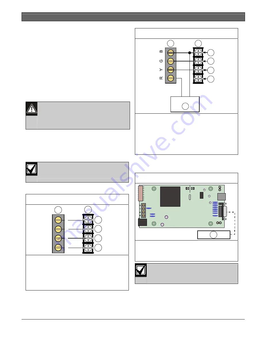
Connect the DX4010V2 to the control panel data and
auxiliary power sources as shown in
Figure 2
.
Figure 2: Control Panel Connections
1
2
3
4
5
6
B
G
Y
R
1-
DX4010V2 data bus
2-
Control panel data bus
3-
Option AUX common/SDI common (black)
4-
Option data/SDI B (green)
5-
Option data/SDI A (yellow)
6-
Option AUX power +/SDI power (red)
If an external 12 VDC power supply is used, wire as
shown in
Figure 3.
Figure 3: External Power Supply Connections
+
-
1
2
3
4
5
6
7
1-
DX4010V2 data bus
2-
Control panel data bus
3-
Option AUX common/SDI common (black)
4-
Option data/SDI B (green)
5-
Option data/SDI A (yellow)
6-
Option AUX power +/SDI power (red)
7-
External 12 VDC power supply
Figure 4
shows serial device-to-DX4010V2
connections using the DB9 DTE RS-232 connector
(P6).
Figure 4: Serial Device Connections
SER
Rx
Tx
BUS
Rx Tx
LED
P2
P3
1
DB9 GND
ENABLE
P1
1-
Serial (RS-232) device such as a PC (with
RPS, BIS, PC9000, or other third party
application) or a serial printer for supported
control panels.
Refer to
Section 7.0 DB9 DTE RS-232
Connector (P6)
on page 10 for additional
information.


