background image

DIVAR IP 6000 (3U)

Recovering the unit | en

29

Bosch Sicherheitssysteme GmbH

Installation Manual

2016.08 | V2.1 | DOC

7

Recovering the unit

Following procedure describes how to restore the factory default image.

To restore the unit to factory default image

1.

Turn on the unit and insert the system recovery DVD.

Notice!

Make sure that a VGA monitor, a keyboard and a mouse are connected to the unit.

2.

Press any key when prompted to start the recovery environment from DVD.

Note:

 Press any key only to start the recovery environment. Do not press any key during

the setup process.

3.

Select one of the following:

Initial Factory Setup (all data on the system will be lost)

(restores to factory default image and deletes all data on the hard drives)
or

System Recovery (back to Factory Defaults)

(restores to factory default image; data on the hard drives will not be deleted)

Note:

Windows performs the setup. The screen displays the percentage of the process.

Notice!

Do not turn off the unit during the process. This will damage the Recovery media.

4.

The unit starts from the Recovery media. If the setup is successful, press 

Yes

 to restart

the system.

5.

Windows performs the initial setup of the operating system. The unit restarts after
Windows has completed the setup.

6.

After the restart of the unit, the factory default settings are installed and the Windows
logon screen is displayed.
The factory default settings are:

IP address: DHCP (Fallback: 192.168.0.200)

Subnet mask: 255.255.255.0

User: BVRAdmin

Password: WSS4Bosch
Summary of Contents for DIP-61F0-00N

Page 1: ...DIVAR IP 6000 3U DIP 61F0 00N DIP 61F3 16HD DIP 61F4 16HD DIP 61F6 16HD DIP 61F8 16HD en Installation Manual ...

Page 2: ......

Page 3: ...ply LEDs 16 4 Rack installation 18 4 1 Unpacking the system 18 4 2 Preparing for setup 18 4 2 1 Choosing a setup location 18 4 2 2 Rack precautions 18 4 2 3 General system precautions 19 4 2 4 Rack mounting considerations 19 4 3 Rack mounting instructions 19 4 3 1 Identifying the sections of the rack rails 20 4 3 2 Separating the sections of the rack rails 20 4 3 3 Installing the inner rails on th...

Page 4: ...nstalling a hard drive into a front drive bay 38 10 5 Identifying a faulty SSD drive 38 10 6 Installing a SSD hard drive into a rear drive bay 38 10 6 1 Removing a hard drive from the rear drive bay 38 10 6 2 Installing a hard drive into a rear hard drive carrier 39 10 6 3 Installing a hard drive into a rear drive bay 40 10 7 Replacing the DVD ROM drive 40 10 8 Replacing the front port panel 40 10...

Page 5: ... not wear loose clothing such as neckties and unbuttoned shirt sleeves which can come into contact with electrical circuits or be pulled into a cooling fan Remove any jewelry or metal objects from your body which are excellent metal conductors that can create short circuits and harm you if they come into contact with printed circuit boards or areas where power is present After accessing the inside...

Page 6: ... have UL CSA shown on the code for any other electrical devices Warning Lithium battery Batteries that have been inserted wrongly can cause an explosion Always replace empty batteries with batteries of the same type or a similar type recommended by the manufacturer Handle used batteries carefully Do not damage the battery in any way A damaged battery may release hazardous materials into the enviro...

Page 7: ... wet basement near a swimming pool in an outdoor installation or in any area classified as a wet location To reduce the risk of fire or electrical shock do not expose this unit to rain or moisture Never push objects of any kind into this unit through openings as they may touch dangerous voltage points or short out parts that could result in a fire or electrical shock Power supply cords should be r...

Page 8: ...rom the system Do not work alone when working with high voltage components Disconnect the power cables before installing or removing any components from the computer including the backplane When disconnecting power you should first turn off the system and then unplug the power cords from all the power supply modules in the system Disconnect the power cable before installing or removing any cables ...

Page 9: ...ntil ready for use Touch a grounded metal object before removing the board from the antistatic bag Do not let components or printed circuit boards come into contact with your clothing which may retain a charge even if you are wearing a wrist strap Handle a board by its edges only Do not touch its components peripheral chips memory modules or contacts When handling chips or modules avoid touching t...

Page 10: ...lace only with the same or equivalent type recommended by the manufacturer Dispose of the replaced battery in an environmentally friendly way and not with other solid waste Refer all servicing to qualified service personnel Do not place this unit on an unstable stand tripod bracket or mount The unit may fall causing serious injury and or serious damage to the unit Information on sales delivery sto...

Page 11: ... not installed and used in accordance with the manufacturer s instruction manual may cause harmful interference with radio communications Operation of this equipment in a residential area is likely to cause harmful interference in which case you will be required to correct the interference at your own expense ...

Page 12: ... Sicherheitssysteme GmbH 2 About this manual This manual is written for professional system integrators and PC technicians It provides information for the installation and use of the chassis Installation and maintenance should be performed by experienced and qualified technicians only ...

Page 13: ...chassis includes 16 hard drive bays and comes with a DVD ROM drive The chassis supports a 3U backplane For empty chassis the hard drives must be purchased separately For the latest shipping lists see the datasheet in the online product catalogue 3 2 2 Fans The built in fans provide 100 cooling redundancy aided by an adjustable air shroud The fans are controlled through IPMI Intelligent Platform Ma...

Page 14: ...ly accessible hard drives display status lights The power supply displays status lights visible from the back of the chassis Front view 1 9 2 6 3 7 4 5 8 1 2x USB 2 0 ports 2 Power failure 3 Information LED 4 NIC1 NIC2 5 HDD drive activity 6 Power 7 Reset 8 Power on off 9 Drive carrier LEDs green access to this drive red drive failure Rear view 1 5 2 6 3 7 4 1 2x power supply modules 2 2x redundan...

Page 15: ...emoves the main power but keeps standby power supplied to the system Therefore you must unplug system before servicing 3 3 2 Control panel LEDs The control panel located on the front of the chassis has LEDs to provide you with critical information related to different parts of the system This section explains what each LED indicates when illuminated Power failure A flashing LED indicates a power f...

Page 16: ... SATA drive SCSI drive and or DVD ROM drive activity Power Indicates power is being supplied to the system s power supply units This LED should normally be illuminated when the system is operating 3 3 3 Drive carrier LEDs LED color Blinking pattern Behavior for device ActivityLED Blue Solid On SAS drive installed Blue Blinking I O activity StatusLED Red Solid On Failed drive for SATA NVMe with RST...

Page 17: ...H Installation Manual 2016 08 V2 1 DOC Blinking Amber When blinking the system power supply temperature has reached 63 C The system will automatically turn off when the power supply temperature reaches 70 C and restart when the power supply temperature goes below 60 C ...

Page 18: ...ient airflow and ease in servicing Notice This equipment is intended for installation in Restricted Access Location or equivalent Notice This product is not suitable for use with visual display work place devices acccording to 2 of the the German Ordinance for Work with Visual Display Units 4 2 2 Rack precautions Warning To prevent bodily injury when mounting or servicing this unit in a rack you m...

Page 19: ...nt in an environment compatible with the manufacturer s maximum rated ambient temperature Tmra Reduced airflow Equipment should be mounted into a rack so that the amount of airflow required for safe operation is not compromised Mechanical loading Equipment should be mounted into a rack so that a hazardous condition does not arise due to uneven mechanical loading Circuit overloading Consideration s...

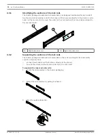
Page 20: ...ter rail has two sections that can slide and adjust to fit your rack depth 1 2 1 Right side inner rail 2 Right side outer rail 4 3 2 Separating the sections of the rack rails The chassis package includes two rail assemblies in the rack mounting kit Each assembly consists of two sections an inner fixed chassis rail that secures directly to the chassis an outer fixed rack rail that secures directly ...

Page 21: ...eft and right inner rails They are labeled 2 Place the inner rail firmly against the side of the chassis aligning the hooks on the side of the chassis with the holes in the inner rail 3 Slide the inner rail forward toward the front of the chassis until the quick release bracket snaps into place securing the rail to the chassis 4 Optionally you can further secure the inner rail to the chassis with ...

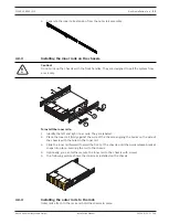
Page 22: ...k Take care that the proper holes are used so the rails are level If desired use screws to secure the rear of the outer rail to the rear of the rack 6 Repeat for the other outer rail 4 3 5 Installing the chassis in the rack Warning Stability hazard Before sliding the unit out for servicing make sure that the rack stabilizing mechanism is in place or the rack is bolted to the floor Failure to stabi...

Page 23: ...vicing make sure that the rack stabilizing mechanism is in place or the rack is bolted to the floor Failure to stabilize the rack can cause the rack to tip over Warning Do not pick up the unit with the front handles The handles are designed to pull the system from a rack only Notice Mounting the chassis into the rack requires at least two people to support the chassis during installation Please fo...

Page 24: ...ust enough space to accommodate the width of the Telco rack Finish by sliding the chassis into the rack and tightening the brackets to the rack 4 4 Turning on the system To turn on the system 1 Plug the power cord from the power supply unit into a high quality power strip that offers protection from electrical noise and power surges We recommended using an uninterruptible power supply UPS 2 Press ...

Page 25: ...figured with the RAID utility prior to initial software setup See also RAID setup page 27 5 2 Setup instruction By default the virtual network adapter the two physical NIC ports are teamed by default is configured to obtain a valid network address from a DHCP server in the local network If there is no DHCP server in the network the system will use the following network settings IP address 192 168 ...

Page 26: ...e network settings you want change 3 Change the IP address 5 4 Standard system configuration The system is delivered with the fully configured iSCSI target and pre configured LUNs The default target name is TG0 and holds all of the iSCSI LUNs The naming convention for the LUNs is VHDxx vhdx where xx ranges from 01 up to n depending on the system used The default setup allows every iSCSI Initiator ...

Page 27: ...k the MegaRAID Storage Manager icon 5 Enter user name and password and then click Login User name BVRAdmin Password customer dependent default WSS4Bosch 6 Click Create Virtual Drive then click Advanced mode 7 Select RAID 5 as RAID level default configuration and follow the steps in the Virtual Drive wizard 8 Select and add all hard drives that are part of the RAID group default all 9 Click Create ...

Page 28: ... on the screen The display appears before Windows starts 3 In the MegaRAID Configuration Utility program select Create Virtual Drive 4 Apply the following settings RAID Level RAID 5 Under Advanced settings Strip Size 64KB Write Policy Write Back Note All other settings remain unchanged 5 Select all hard drives that are part of the RAID group 6 Start the virtual drive initialization 7 Exit the Mega...

Page 29: ...ill be lost restores to factory default image and deletes all data on the hard drives or System Recovery back to Factory Defaults restores to factory default image data on the hard drives will not be deleted Note Windows performs the setup The screen displays the percentage of the process Notice Do not turn off the unit during the process This will damage the Recovery media 4 The unit starts from ...

Page 30: ...onfiguration of hardware and software is available on the online product catalogue Documentation and software for Bosch Security Systems products can be found in the online product catalogue as follows 4 Open any browser enter www boschsecurity com select your region and your country start a search for your product select the product in the search results to show the existing files ...

Page 31: ...systeme GmbH Installation Manual 2016 08 V2 1 DOC 9 OSS licenses This chapter provides an overview on used Open Source Licenses in DIVAR IP 6000 The license packages are either used completely or only some parts within a package are used 9 1 MIT iniparser ...

Page 32: ...32 en OSS licenses DIVAR IP 6000 3U 2016 08 V2 1 DOC Installation Manual Bosch Sicherheitssysteme GmbH 9 2 MS PL MSDN Library ...

Page 33: ...DIVAR IP 6000 3U OSS licenses en 33 Bosch Sicherheitssysteme GmbH Installation Manual 2016 08 V2 1 DOC 9 3 NTP License NTP Project ...

Page 34: ...icing this chassis 10 1 Replacement components Although not frequently you may need replacement parts for your system To ensure the highest level of professional service and technical support you must register the systems according to the instructions available as part of the shipment as well as online from the Bosch product catalog 10 2 Removing power from the system Before performing some setup ...

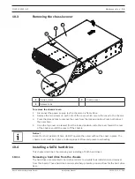
Page 35: ...me time 4 Once the top cover is released from the locked position slide the cover toward the rear of the chassis and lift the cover off the chassis Notice Except for short periods of time do NOT operate the server without the cover in place The chassis cover must be in place to allow proper airflow and prevent overheating 10 4 Installing a SATA hard drive This chapter describes the removing and in...

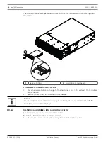
Page 36: ...lease button to the right of the hard drive carrier This extends the hard drive carrier handle 2 Use the handle to pull the drive out of the chassis Notice Except for short periods of time swapping hard drives do not operate the unit with the hard drives removed from the bays 10 4 2 Installing a hard drive into a hard drive carrier The hard drives are mounted in hard drive carriers To install a ha...

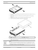
Page 37: ...d the hard drive 5 Secure the hard drive to the hard drive carrier using six screws 1 Hard drive carrier 2 SATA hard drive 6 Replace the hard drive carrier into the chassis bay Make sure that the hard drive carrier handle is completely closed Notice We recommend using the respective Bosch hard disk drives The hard disk drives as one of the critical component are carefully selected by Bosch based o...

Page 38: ... and replace SSD drives 1 Turn on the unit and log on as user BVRAdmin The default screen is displayed 2 Double click the Intel Rapid Storage icon on the screen 3 Check the status of the listed SSD drives and note the port numbers SATA port 0 refers to the SSD located in the upper tray SATA port 1 refers to the SSD located in the lower tray 4 After you have identified the faulty SSD drive open the...

Page 39: ...ier 3 Insert a hard drive into the hard drive carrier with the printed circuit board side facing down and the connector end toward the rear of the carrier 4 Align the mounting holes in both the hard drive carrier and the hard drive Note There are mounting holes in the hard drive carrier marked SAS or SATA to aid in correct installation 5 Secure the hard drive to the hard drive carrier with four sc...

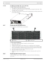
Page 40: ...ich is pre installed 2 1 1 DVD ROM 2 Front port panel To replace the DVD ROM drive 1 Turn off the unit and if necessary remove the unit from the rack 2 Remove the chassis cover 3 Unplug the drives power and data cables from the motherboard and or backplane 4 Locate the locking tab at the rear on the left when viewed from front of the DVD ROM drive Push the tab toward the drive and push the drive u...

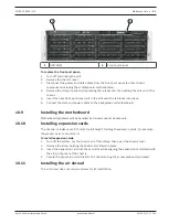
Page 41: ...bles to the backplane and motherboard 10 9 Installing the motherboard Motherboard problems will be handled by trained support people only 10 10 Installing expansion cards The chassis includes seven PCI slots for full height full length expansion cards for example the graphic card or sound card To install expansion cards 1 Turn off the system lay the chassis on a flat surface then open the chassis ...

Page 42: ... obstruct airflow in and out of the chassis In addition if you are using a front bezel make sure the bezel s filter is replaced periodically 2 Do not operate the system without drives or drive trays in the drive bays Use only recommended material 3 Make sure no wires or foreign objects obstruct air flow through the chassis Pull all excess cabling out of the airflow path or use shorter cables The c...

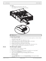
Page 43: ...se tab 2 Airflow direction indicator 5 Place the new fan into the vacant space in the housing while making sure the arrows on the top of the fan indicating air direction point in the same direction as the arrows on the other fans 6 Reconnect the power cord turn on the system and make sure that the fan is working properly before replacing the chassis cover 7 Replace the chassis cover 10 13 Replacin...

Page 44: ...l the power supply out using the handle provided 5 Replace the failed power module with the same model 6 Push the new power supply module into the power bay until you hear a click 7 Plug the AC power cord back into the module and turn on the unit 10 14 Monitoring the system The system provides tools for health monitoring To activate the monitoring functionality 1 Turn on the unit and log on as use...

Page 45: ...ontact in case of failure but the Service and Support obligations are fulfilled by the manufacturer or a partner In order to enable the manufacturer s Service and Support organization to fulfill the defined Service Levels the system must be re registered Otherwise the defined service level cannot be provided but only best effort A description what information is required and where to send is inclu...

Page 46: ...e GmbH Opening Hours Monday to Friday 08 30 17 30 RMA Contact EMEA Bosch Security Systems C o EVI Audio GmbH Ernst Heinkel Str 4 94315 Straubing GERMANY Contact person RA Desk Supervisor Phone 49 9421 706 366 Fax n a E mail rmadesk stservice de bosch com Opening Hours Monday to Friday 07 00 18 00 ...

Page 47: ......

Page 48: ...Bosch Sicherheitssysteme GmbH Robert Bosch Ring 5 85630 Grasbrunn Germany www boschsecurity com Bosch Sicherheitssysteme GmbH 2016 ...

Reviews: