Bosch Security Systems | 2007-11 | 9922 141 70691 en
DCN Wireless
| Installation and User Instructions | Contribution Devices
en
| 86
15.3 External
connections
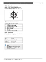
Connect the pluggable microphone to compatible
devices with the microphone plug (refer to figure 15.2).
15.4 Operation
The color of the indicator ring shows the condition of
the microphone (refer to table 15.5).
figure 15.2: Microphone plug, connection
table 15.4: Microphone plug, connection
Pin
Signal
1
Indicator ring, red (cathode)
2
Indicator ring common (anode)
3
Microphone
4
Microphone GND
5
Shielding
6
Indicator ring, green (cathode)
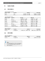
table 15.5: Condition
Color
Condition
Red (on)
Microphone active
Red (flash)
Last minute of speech time
Green (on)
Request-to-speak
Green (flash)
First request
Note
When the microphone is connected to a
DCN-IDESK, it can only show that the
microphone is activated.
6
1
2
5
4
3


