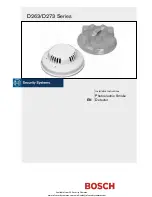
D263/D273 Series
| Installation Instructions | 3.0
Wiring
Refer to your control panel’s installation
instructions for EOL resistor selection.
Figure 3:
D263 Series/D263TH Wiring
2
1
1
2 3 4
+
IN
–
IN
–
OUT
+
OUT
1
2 3 4
+
IN
–
IN
–
OUT
+
OUT
+
–
1 -
Alarm loop
2 -
EOL resistor
Figure 4:
D273ES/D273THES Wiring
1 2
3 4
5 6
7 8
Input Voltage
10 to 30 VDC
+
IN
+
OUT
–
IN
–
OUT
Alarm Contacts
Normally Open
Smoke Detector
Power
Alarm
Loop
+
–
+
–
+
IN
+
OUT
–
IN
–
OUT
9 10
EOL
Relay
E+
E
1
2
3
1 -
Last detector
2 -
Control panel
3 -
EOL resistor
Figure 2:
Mounting a D263/D273 Series
Detector
1
2
3
1 -
Wire entrance
2 -
Locking tab
3 -
Mounting holes
3.0 Wiring
Before connecting or disconnecting any
D263/D273 Series Detectors, remove all
AC and battery power from the FACP.
Failure to do so can result in personal injury
and damage to the equipment.
The terminal block is removable. It might be easier to
remove the terminal block from the detector before making
the wire connections. Remove the terminal block by pulling
it back and then pulling up. Refer to Figures 3 through 8 on
pages 3 through 5 for wiring details.
When all wiring connections are made, connect the detector
to the mounting plate by twisting it clockwise into place.
Figure 5:
D273/D273TH Wiring
1 2
3 4
5 6
7 8
Input Voltage
10 to 30 VDC
+
IN
+
OUT
–
IN
–
OUT
Alarm Contacts
Normally Open
Smoke Detector
Power
Alarm
Loop
+
–
+
–
+
IN
+
OUT
–
IN
–
OUT
2
Black
Yellow (+24 V) or
Red (+12 V)
Blue
Blue
1
2 3
4 5 6
7 8
Input Voltage
10 to 30 VDC
Alarm Contacts
Normally Open
+
IN
+
OUT
–
IN
–
OUT
+
IN
+
OUT
–
IN
–
OUT
1
3
4
1 -
Last detector
2 -
Control panel
3-
EOL
resistor
4 -
D275 EOL Power Supervision Module
Bosch Security Systems, Inc. | 02/06 | 31341J
Available from A1 Security Cameras
www.a1securitycameras.com email: [email protected]
3


