background image

CP156B

Installer Reference Guide

4

Bosch Security Systems    01/19    CP156BIRG  FTR1.1

Hold Down Functions

The CP156B keypad supports the following hold down 

functions.  These functions will only work if the keypad 

has been assigned to an area.  When keypads are in-

stalled outside the premises and are being used for area 

control, it is recommended that you disable the emer-

gency key functions to prevent nuisance alarms.  

See the Devices-Keypads & Readers-Emergency Keys 

menu option in panel programming to disable these 

features.

Hold Down Functions

Function

Meaning

PANIC 

ALARM

Press and hold both the [1] and [3] 

keys down for 2 seconds to initiate 

a panic alarm.

FIRE 

ALARM

Press and hold both the [4] and [6] 

keys down for 2 seconds to initiate 

a fire alarm.

MEDICAL 

ALARM

Press and hold both the [7] and [9] 

keys down for 2 seconds to initiate 

a medical alarm.

All ON

Enter a valid PIN and then press 

and hold down the [#] key, the 

system will turn On or Arm all areas 

that the user belongs to at the 

same time.

All OFF

Enter a valid PIN and then press 

and hold down the [*] key, the 

system will turn Off or Disarm all 

areas that the user belongs to at 

the same time.

Table 4: Hold Down Functions

i

Note

  The hold down 4 - Chime Mode and hold down 

6 - Answer Incoming Call features are not currently 

supported from the CP156B keypad.

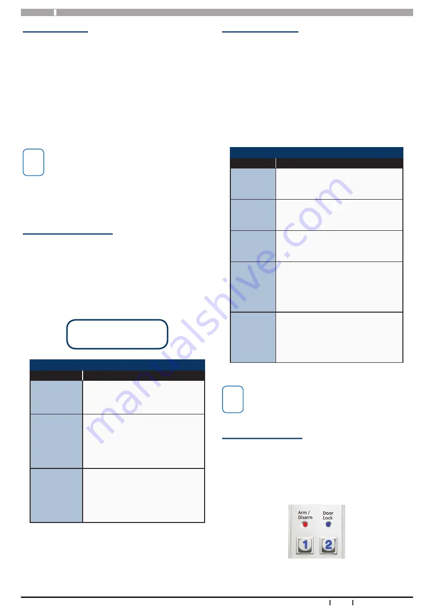
Keypad LED Indicators

The CP156B keypad includes RED/ GREEN and BLUE indi-

cator LEDs which provide visual feedback during system 

operation. 

The Red/Green indicators will show alarm &/or area sta-

tus. The Blue indicator will show door status.


Figure 7:  LED Indicators

Keypad Operation

The CP156B keypad can be configured to provide sys-

tem area control, door access control or both depending 

on the installation requirements.  

As there is no LCD display on the keypad, feedback 

is provided via the red/green and blue LED’s and the 

keypad sounder.  

The CP156B also includes an egress input and lock out-

put which can be used to control door access if required.

i

Note

  Using the on board lock output is not recommend-

ed when the CP156B is being used on an external 

wall of the building.  In this case it is recommended 

that you run the lock control wires directly to an 

output located on the main panel or output ex-

pander module located inside the building.

Keypad Button Functions

The CP156B keypad consists of 12 individual buttons 

which are used to enter PIN and control the system.  

Some buttons have a secondary functions that are acti-

vated by holding the button down for two seconds.  

The [#] and [*] buttons perform the same functions as 

the ON and OFF buttons on the standard display keypad.

#

 Button = ON Button

*

 Button = OFF Button

Keypad Button Functions

Button

Description

[0] to [9] 

The numeric buttons allow you 

to enter PIN numbers and other 

functions when required.

[#]

To arm the system enter the user 

PIN followed by the [#] key. 
The [#] key performs the same 

function as the [ON] button on 

display enabled keypads.  

[*]

To disarm the system enter the 

user PIN followed by the [*] key. 
The [*] key performs the same  

function as the [OFF] button on 

display enabled keypads.  

Table 3: Button Functions

Summary of Contents for CP156B

Page 1: ...CP156B External Metal Keypad with Smart Card Reader Security System Installer Reference Guide EN Security Systems ...

Page 2: ...ach keypad fitted to the system must be assigned a unique address on the LAN The CP156B includes a DIP switch for quick address selection The following table shows the address setting for each keypad as well as the number of keypad devices each panels can support CP156B Keypad Compatibility Panels Supported Version Keypads Supported Solution 6000 2 25 Up to 16 Table 1 CP156B Compatibility CP156B E...

Page 3: ...sing table 2 Note Each keypad on the system must have a unique address Step 4 Attach the connection cable to the keypad by plugging in the con nector Note the connector is polarised and will only plug in when correctly aligned Do not use excessive force Step 5 Make sure the cable grommet is fitted correctly to insure a correct water resistant seal Step 6 Carefully hook the keypad to the back plate...

Page 4: ...ystem operation The Red Green indicators will show alarm or area sta tus The Blue indicator will show door status Figure 7 LED Indicators Keypad Operation The CP156B keypad can be configured to provide sys tem area control door access control or both depending on the installation requirements As there is no LCD display on the keypad feedback is provided via the red green and blue LED s and the key...

Page 5: ... be assigned to the same door as the keypad If both alarm area and door control is required then you will need to assign a home area and a door to the keypad i Note The CP156B LED indicators will only display the status of the programmed home area You can not move between areas from this keypad If you require multiple area status visibility you should use a display keypad like the CP700B Keypad Al...

Page 6: ...C door strikes the back EMF energy generated when the lock is released should be shunted with a reverse diode and is not always provided by the door strike manufacturer The Egress input Green Wire on the CP156B keypad al lows you to simplify the wiring required to implement an egress button on the inside of the door The egress input triggers the lock output on the keypad by operating the associate...

Page 7: ...t incorporates both the EM and Smart Card formats with identical 40bit credential allowing the one token to be used across different technologies You may have a site that is running the dated EM for mat but now installing a new site with the high security Smart Card Format and want to use the same tokens across both sites PR301 Smart Card Token PR350 Smart Card PR370 Dual Smart Card Token PR365 Ad...

Page 8: ...ct to change without notice CP156B Installer Reference Guide 8 Bosch Security Systems 01 19 CP156BIRG FTR1 1 1 ON K E 2 3 4 5 Not Used EGRESS INPUT N O BK Black RD Red WH White BL Blue YL Yellow GY Grey GN Green RD RED BK BLACK WH WHITE BL BLUE LAN LAN LAN A LAN B BRN BROWN ORG ORANGE PPL PURPLE GN GREEN RELAY NO RELAY COM RELAY NC EGRESS YL YELLOW GY GREY NOT USED NOT USED Control Panel Wiring Le...

Page 9: ...CP156B Installer Reference Guide 9 Bosch Security Systems 01 19 CP156BIRG FTR1 1 This page left intentionally blank ...

Page 10: ...CP156B Installer Reference Guide 10 Bosch Security Systems 01 19 CP156BIRG FTR1 1 This page left intentionally blank ...

Page 11: ...CP156B Installer Reference Guide 11 Bosch Security Systems 01 19 CP156BIRG FTR1 1 This page left intentionally blank ...

Page 12: ...Bosch Security Systems Level 2 21 Solent Circuit Baulkham Hills NSW 2153 Australia Phone 1300 026 724 www boshsecurity com au 2019 Bosch Security Systems CP156BIRG Issue FTR1 1 ...

Reviews: