Commissioning
25
Condens 7000 F – 6720871560 (2019/11)
7.3
Recording gas parameters
Ask your gas supplier to advise you of the gas parameters (Wobbe index
and calorific value) and record these in the commissioning report
(
Chapter 17.6, page 63).
If the boiler is to be replaced in existing systems:
▶ Consult gas suppliers to ensure that the nominal gas pressure
according to table 10, page 28 is adhered to.
7.4
Checking device equipment
The burner is supplied ready for operation and is adapted to the locally
available gas type (natural gas E/LL) using the supplied gas flow restrictors.
▶ Check with the relevant gas supplier which gas group or sub-group
(gas type) is supplied.
▶ Determine, based on the gas parameters requested from the gas
supplier and the information in the table 8 and 9, which gas flow
restrictor is required.
▶ Check whether the required gas flow restrictor is installed.
▶ If required, replace the gas flow restrictor during commissioning
(
Chapter 7.5).
7.5
Converting the boiler to a different gas type
7.5.1
Converting to another type of natural gas
The boiler is converted to a different gas type by replacing the installed
gas flow restrictor. The air/gas ratio does not need to be adjusted,
the air/gas ratio control valve is adjusted and sealed.
▶ Switch off the heating system via the ON/OFF switch at
the control unit (
Technical documentation for control unit).
▶ Close gas isolator.
▶ Remove upper boiler front panel and left side panel
(
Chapter 11.1, page 31).
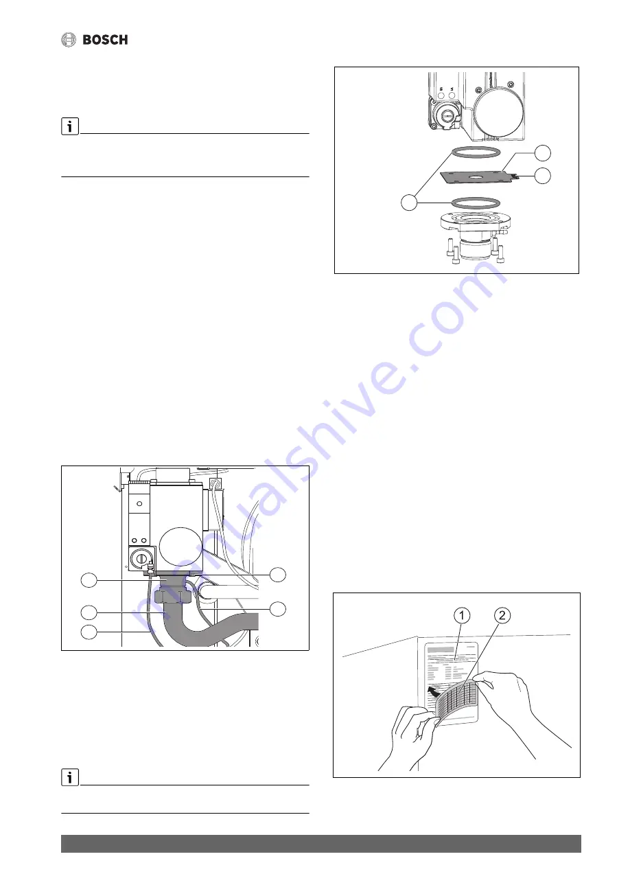
Fig. 25 Removing the gas flow restrictor
[1]
Compensation line
[2]
Gas pipe
[3]
Connection flange
[4]
Allen screws (4x)
[5]
Test line for gas outlet pressure
▶ Remove the four Allen screws [4] at the connection flange [3] and
carefully move the flange away from the valve. In doing so, avoid
damaging and/or buckling the gas pipe [2].
If the connection is subject to mechanical stress, the gas pipe can be
removed to make disassembly easier.
Fig. 26 Replacing the gas flow restrictor
[1]
O-ring (2x)
[2]
Gas flow restrictor
[3]
Labelling
▶ Remove the gas flow restrictor [2] and replace with the
corresponding gas flow restrictor for the supplied gas type
(
Tab. 8).
▶ Check whether the required flow restrictor is used, compare the
diameter indicated on the flow restrictor with the corresponding
value in Tab. 8.
▶ Check O-rings [1] for damage and replace if necessary.
▶ Place the O-rings in the grooves provided. Make sure they are seated
correctly.
▶ Insert the gas flow restrictor with the label [3] facing upwards and
tab pointing to the right.
▶ Mount the connection flange and gas flow restrictor including all
O-rings with the 4 Allen screws (for torques and replacement interval
▶ Make sure the test cables for compensation [1] and gas outlet
pressure [5] are correctly seated (
▶ Carry out all commissioning work and complete the commissioning
report (
▶ Affix the label provided for the supplied gas type, according to the
gas flow restrictor, over the corresponding area on the existing boiler
data plate (
Fig. 27, [1]) (
Fig. 27, [2]).
▶ Store the restrictor that has been taken out in a safe place.
Fig. 27 Updating the data plate
[1]
Boiler data plate
[2]
Label
0010014080-001
4
3
5
1
2
0010014176-002
1
2
3
0010012477-002


