


Preparing for installation
9
Compress 7001i AW – 6721835318 (2021/09)
4.2
For drainage
Remove condensate via a frost-free drain of the heat pump, possibly
equipped with pipe trace heating. The drain must slope sufficiently to
prevent water from accumulating in the pipe.
The condensate can be routed to either a gravel bed, a stone box or into
a rainwater gully.
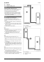
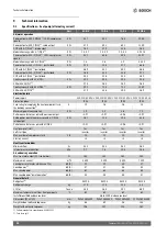
Fig. 12 Condensate pipe in gravel bed
[1]
Concrete foundations
[2]
Shingle 300 mm
[3]
Condensate tube 32 mm
[4]
Gravel bed
4.3
Minimum volume and execution of the heating
system
To safeguard the heat pump function and avoid an excessive number of
start/stop cycles, incomplete defrosting and unnecessary alarms, it
must be possible to store a sufficient amount of energy in the system.
This energy is stored in the water volume of the heating system, and also
in the components of the system (radiators) and concrete floor
(underfloor heating system).
As the requirements for different heat pump installations and heating
systems vary considerably, a minimum water volume in litres is generally
not specified. Instead, the system volume is considered to be sufficient
if certain conditions are met.
Underfloor heating system without buffer cylinder
A room temperature-dependent control unit should be installed in the
largest room (reference room) instead of room thermostats. Small floor
areas can lead to the auxiliary heater being activated in the final phase of
the defrosting process.
• ≥ 6 m
2
floor area required for heat pump 5 OR-S – 9 OR-S.
• ≥ 22 m
2
floor area required for heat pump 13 OR-S – 17 OR-T.
To ensure maximum energy savings and avoid auxiliary heater operation,
the following configuration is recommended:
• ≥ 30 m
2
floor area for heat pump 5 OR-S – 9 OR-S.
• ≥ 100 m
2
floor area for heat pump 13 OR-S – 17 OR-T.
System with radiators without mixer and buffer cylinder
If the system only contains a few radiators, the auxiliary heater may be
activated in the final phase of the defrosting process. The radiator
thermostats must be opened fully.
• ≥ 1 radiator with 500 W rating required for heat pump 5 OR-S – 9
OR-S.
• ≥ 4 radiators each with roughly 500 W rating required for heat pump
13 OR-S – 17 OR-T.
To ensure maximum energy savings and avoid auxiliary heater operation,
the following configuration is recommended:
• ≥ 4 radiators with 500 W rating for heat pump 5 OR-S – 9 OR-S.
Heating system with underfloor heating system and radiators in
separate heating circuits without buffer cylinders
A room temperature-dependent control unit should be installed in the
largest room (reference room) instead of room thermostats. Small floor
areas or only a few radiators in the system can lead to the auxiliary heater
being activated in the final phase of the defrosting process.
• ≥ 1 radiator with 500 W rating required for heat pump 5 OR-S – 9
OR-S.
• ≥ 4 radiators each with roughly 500 W rating required for heat pump
13 OR-S – 17 OR-T.
Although a minimum floor area is not required for the underfloor heating
circuit, to avoid auxiliary heater operation and achieve optimum energy
savings, additional heating thermostats or several valves of the
underfloor heating system must be at least partially open.
Only heating circuits with mixer
A buffer cylinder is essential in heating systems consisting only of
heating circuits with mixer.
• Required volume for heat pump 5 OR-S – 9 OR-S = ≥ 50 litres.
• Required volume for heat pump 13 OR-S – 17 OR-T = ≥ 100 litres.
Only fan convectors
To prevent the auxiliary heater from being activated in the final phase of
the defrosting process, a buffer storage tank with a capacity of ≥ 10 l is
required.
Cooling mode
If cooling mode is activated and run in combination with fan coils it is
recommended to add a buffer cylinder ≥ 100 litres in the system for best
performance and comfort.
2
4
3
1
900 mm


