


Installation
Compress 7001i AW – 6721835318 (2021/09)
12
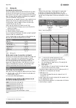
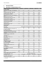
Table 6 Pipe dimensions and maximum pipe lengths (single section) for connecting the heat pump to the indoor unit AWM
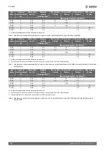
Table 7 Pipe dimensions and maximum pipe lengths (single section) when connecting the heat pump to the AWB indoor unit with mixer for the external
auxiliary heater
Table 8 Pipe dimensions and maximum pipe lengths (single section) for connecting the heat pump to the AWE indoor unit with integrated electric
booster heater
Heat
pump
Delta heat
transfer medium
(K)
Nominal flow
rate (l/s)
Maximum
pressure
reduction (kPa)
1)
1) For pipes and components between the heat pump and indoor unit.
AX20 inside Ø
15 (mm)
AX25 inside Ø
18 (mm)
AX32 inside Ø
26 (mm)
AX40 inside Ø
33 (mm)
Maximum pipe length [A, 16] PEX (m)
5 OR-S
5
0.32
68
14
30
7 OR-S
5
0.33
55
7
16.5
30
9 OR-S
5
0.43
40
4
10.5
30
13 OR-S
5
0.62
56
7
30
30
17 OR-T
5
0.81
18
7.5
30
Heat
pump
Delta heat
transfer medium
(K)
Nominal flow
rate (l/s)
Maximum
pressure
reduction (kPa)
1)
1) For pipes and components between the heat pump and indoor unit.
AX20 inside Ø
15 (mm)
AX25 inside Ø
18 (mm)
AX32 inside Ø
26 (mm)
AX40 inside Ø
33 (mm)
Maximum pipe length [A, 16] PEX (m)
2)
2) The installation of a 3-way valve in the DHW circuit of the system was factored into the calculation of the pipe lengths.
5 OR-S
7
0.32
50
8,5
21
30
7 OR-S
7
0.32
52
8,5
22
30
9 OR-S
7
0.32
54
22.5
30
13 OR-S
7
0.56
40
30
30
17 OR-T
7
0.58
40
30
30
Heat
pump
Delta heat
transfer medium
(K)
Nominal flow
rate (l/s)
Maximum
pressure
reduction (kPa)
1)
1) For pipes and components between the heat pump and indoor unit.
AX20 inside Ø
15 (mm)
AX25 inside Ø
18 (mm)
AX32 inside Ø
26 (mm)
AX40 inside Ø
33 (mm)
Maximum pipe length [A, 16] PEX (m)
2)
2) The installation of a 3-way valve in the DHW circuit of the system was factored into the calculation of the pipe lengths.
5 OR-S
5
0.32
55
9
23
30
7 OR-S
5
0.34
57
8,5
21.5
30
9 OR-S
5
0.43
44
10.5
30
13 OR-S
5
0.63
34
24
30
17 OR-T
5
0.82
10
11
3)
3) This pipe length applies if a diverter valve is not installed in the DHW circuit of the system.
30
3)


