background image

6 720 809 134 (2013/09)

Compress 3000 DW FII

Installation | 11

with the weight distributed equally over its 3 adjustable 
feet).

To ensure faultless operation and easy access to all 
components and connections for service and maintenance, 
maintain the minimum clearances specified in Fig. 6.

Fig. 6

Recommended minimum clearances (mm)

5.2 Installing the appliance

▶ Remove the foil and external protective packaging.
▶ Lift the appliance from its pallet and position it on its final 

plinth.

▶ To correctly align the appliance at the installation location, 

adjust the height of the adjustable feet.

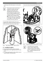
▶ Assure correct positioning of all temperature sensors.

Fig. 7

Temperature sensor at the top of the cylinder

Fig. 8

Temperature sensors (

evaporator plates

 + air inlet)

If the appliance only has one duct (inlet or 
outlet duct), its operation may create 
negative or positive pressure in the 
installation room. If other burners are 
already installed in the same place, please 
bear in mind that the appliance requires a 
clearance of at least 220 cm

2

 for the air inlet 

and outlet in order to operate correctly. 

Note

: The clearance of 220 cm

2

 is required 

for the correct functioning of the heat pump 
only. In addition, you must ensure that the 
burner has the necessary clearance.

500

400

2200

430

6720804054-17.1V

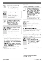
To ensure that the system operates 
faultlessly and the condensate drains 
correctly, the appliance must be aligned 
vertically. The appliance must not tilt more 
than 1°, preferably in the direction of the 
condensate drain.

Summary of Contents for Compress 3000 DW FI Series

Page 1: ...allation instructions before installing the appliance Please read the operating instructions before commissioning the appliance Please observe the safety instructions in the operating instructions The installation location must meet the requirements for sufficient ventilation Installation must only be carried out by an authorised contractor ...

Page 2: ...liance s electrical connection 16 7 Commissioning 17 7 1 Before commissioning 17 7 2 Switching the appliance on off 17 8 Operation 17 8 1 Operation modes 18 8 2 Setting the domestic hot water temperature 18 8 3 Main menu 18 8 4 Prog submenu Operating modes 19 8 4 1 Manual operating mode 19 8 4 2 P1 P2 and P3 operating modes 19 8 4 3 Full operating mode 19 8 4 4 OFF operating mode 19 8 5 Mode subme...

Page 3: ...mperatures 3 C 80 C Minimum maximum water pressure 0 2 bar 2 bar below the value of the installed safety valve Risk of scalding at the hot water draw off points When the appliance is in operation temperatures in excess of 70 C can occur To limit the temperature at the tap install a thermal DHW tempering valve Service The end customer is responsible for safety and environmental compatibility during...

Page 4: ...with a greenhouse potential of 1300 in the Kyoto Protocol Instructions to the customer Explaintothecustomerhowtheapplianceworksandhowto operate it Advise the customer that he she must not make any modifications to the appliance or carry out any repairs on it Safetyofelectricalappliancesfordomesticuseandsimilar purposes The following requirements apply in accordance with EN 60335 1 in order to prev...

Page 5: ...oor installation I Air supply from inside V Vertical installation S Side connections 3 3 Data plate The data plate is located on the rear side of the appliance There you will find details on the appliance performance part numbers approval data the coded date of manufacture FD serial numbers and other specifications 3 4 Description of appliance Appliance for DHW heating with the following propertie...

Page 6: ...20 809 134 2013 09 Compress 3000 DW FII 6 About the appliance 3 5 Dimensions and minimum clearances Fig 2 Appliance dimensions in mm 6720804054 03 1V 670 25 94 331 630 735 1266 916 1835 350 700 735 445 160 ...

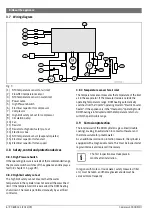
Page 7: ...to condenser 10 Water outlet from condenser 11 Fan 12 Evaporator 13 Condenser gas water heat exchanger 14 Compressor 15 Sensor pocket for DHW temperature sensor 16 Magnesium anode 17 Central heating resistor 18 Adjustable feet 3x 19 Air outlet aperture 20 Air inlet aperture 21 Condensate outlet 22 Circulation pump 23 Front protective covering 24 Housing ring 25 Housing lid 26 Fastening for housing...

Page 8: ...escribed limit If the temperature limit is exceeded the DHW heating shuts down The reset is performed manually by a certified contractor 3 8 3 Temperature sensor for air inlet The temperature sensor measures the temperature of the inlet air in the evaporator If the measured value is outside the operating temperature range DHW heating automatically switchesfromthe Combi operatingmodeto Electricboos...

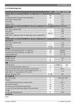
Page 9: ... coefficient COP 2 79 Heat up time h 10 38 Heat loss 24h kWh day 0 97 Air inlet Air flow rate without with pipework fan speed SP1 m3 h 380 300 Air flow rate without with pipework fan speed SP2 m3 h 490 300 Operating temperature C 10 35 Refrigerant circuit Refrigerant R134a g 400 Maximum pressure bar 27 DHW Cylinder capacity l 270 260 Area of heat exchanger internal indirect coil m2 1 3 Maximum out...

Page 10: ...on cause by gas steam or dust Ensure that condensate drains correctly Thesurfacebelowtheappliancemustbestrongenough the appliance weighs about 400 kg when the cylinder is filled Sound pressure level with pipework at a distance of 2 m dB A 40 Dimensions W x H x D mm 700 1835 735 Net weight without packaging kg 108 125 Unit HP270 2E0 HP270 2E1 Table 3 WARNING Transport damage Take care when handling...

Page 11: ...rature sensor at the top of the cylinder Fig 8 Temperature sensors evaporator plates air inlet If the appliance only has one duct inlet or outlet duct its operation may create negative or positive pressure in the installation room If other burners are already installed in the same place please bear in mind that the appliance requires a clearance of at least 220 cm2 for the air inlet and outlet in ...

Page 12: ...6 4 5 3 1 Open flue operation If the heat pump is operated with air from the installation location the volume of the room must be at least 20 m3 5 3 2 Outdoor air operation If the pump is operated with outdoor air the ducts must be protected against the weather using the correct end pieces Fig 9 Equivalent duct length L 1 Air inlet 2 Air outlet 5 4 Connecting the water pipes NOTICE Possible damage...

Page 13: ...pressure control valve to the appliance supply NOTICE Pipes can be damaged if treated incorrectly Do not allow pipes to become contaminated during installation If necessary flush the pipes with water prior to commissioning Prior to installation thoroughly flush water pipes as the water flow could be reduced by contaminants and in case of severe contamination be stopped completely Fit a water filte...

Page 14: ...o the collection area Drain off condensate via a siphon drain Fig 10 2 Fig 10 Condensate collection 1 Condensate drain pipe 2 Outlet siphon 5 8 DHW expansion vessel1 Installan expansion vesselatthewaterconnectionbetween the cylinder and the safety assembly Tab 6 serves as a reference for the selection of an expansion vessel at a reference temperature of 60 C The capacity of the expansion vessel mu...

Page 15: ...g 11 Heating pump 1 Selector switch 2 Air vent screw Select Purg operating mode page 24 chapter 8 6 5 Open the drain screw on the heating pump Fig 11 2 until the water flows steadily and without air bubbles Close the drain screw on the heating pump Wait around 5 minutes until the Purg operating mode has finished Set the selector switch on the heating pump to I The process of draining and filling t...

Page 16: ...er treatment may be needed against corrosion 0 5 LSI 1 5 LSI Langelier Saturation Index Table 7 Water conductivity for sacrificial anodes 130 S cm 1500 S cm Table 8 Water conductivity Do not use fully desalinated distilled or deionised water for this appliance type The appliance may only be installed by an authorised contractor DANGER Risk of electric shock Isolate the appliance from the power sup...

Page 17: ...ection 8 Operation Fig 13 User interface 1 Display 2 Selector keys NOTICE Damage to the appliance After installing the appliance in its final position wait at least 30 minutes before switching it on NOTICE Do not start the appliance without water Only operate the appliance once it has been filled with potable water Once the compressor has been started the appliance must run for at least 5 minutes ...

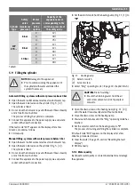
Page 18: ...emperature Press the or button to set the desired value Fig 15 Setting the temperature Press the OK button to confirm the setting 8 3 Main menu Calling up the main menu Press and hold the Menu button for max 3 seconds Fig 16 Calling up the main menu Once you have called up the main menu you can select the following menus submenus Prog Operating modes Manual P1 P2 P3 Full Off Mode Heat types Electr...

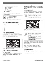
Page 19: ...operatingtimes page 22 8 4 3 Full operating mode In this operating mode two heat appliances are used at the same time the heat pump and the electric booster heater Fig 18 Full operating mode The water temperature can be set to between 30 C and 70 C As soon as the set DHW temperature is reached the appliance switches from the Full operating mode back to the previously set operating mode Quick activ...

Page 20: ...lecting this operating mode means that the heat pump is the only heat appliance used Fig 22 Heat pump operating mode The water temperature can be set to between 30 C and 60 C 8 5 3 Combi operating mode In this operating mode two heat appliances are used depending on the situation the heat pump or the electric booster heater Fig 23 Combi operating mode The water temperature can be set to between 30...

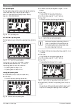
Page 21: ...day of the week using the or button Fig 26 Setting the weekday Confirm by pressing OK The hour flashes on the display Set the hour using the or button Confirm by pressing OK The minutes flash on the display Set the minutes using the or button Confirm by pressing OK The process of setting the clock is complete 8 6 2 Prog Programming of the operating times Inthe Prog submenu youcan settheoperationpe...

Page 22: ...t of the operating time using the and buttons Press OK The end of the first operating time flashes Set the run time using the and buttons Press OK The start of the second operating time flashes Fig 31 Start of the second operating time Set the start of the second operating time using the and buttons Press OK The end of the second operating time flashes Set the run time using the and buttons Press ...

Page 23: ...Leg function Activating the automatic Leg function Call up the Leg function and press OK flashes on the display Press flashes on the display Press OK The Leg function is activated and the first day of the week flashes Set the day of the week for disinfection Select the day using the and buttons Press OK 6720646160 38 1V 1 2 3 4 6720804054 14 1V This function isdeactivatedon theappliance at the fac...

Page 24: ...on without ducts dON installation with ducts Press OK 8 6 5 Purg Drain The Purg functioncanbeusedtodrainwaterfromthesystem Fig 37 Purg function Switching on the Purg function Call up the Purg function and press OK The pump is switched on The display indicates the time remaining until the draining procedure is complete in minutes After 5 minutes the appliance reverts to the previously selected oper...

Page 25: ... least 3 seconds Fig 42 Resetting the system 8 9 Default settings After setting the temperature units and the time the appliance adopts the default settings Heating mode Combi chapter 8 5 Operating mode Manual chapter 8 4 1 Selected temperature 50 C Fig 43 Initial menu 9 Environmental protection Recycling Environmental protection is one of the fundamental company policies of the Bosch Group Produc...

Page 26: ...gnesium anode Check the state of the magnesium anode and replace if necessary 10 3 Cleaning Check and clean the evaporator regularly The air inlet and air outlet apertures must be unobstructed and accessible Checktheairgrille airfilterandairductsregularlyandclean them if necessary 10 4 Condensate pipe Disconnect the condensate hose from the condensate drain Check the drain and or hose for contamin...

Page 27: ... until the water stops flowing out of the safety valve drain tap and the appliance has been completely drained 10 9 Service menu CAUTION Risk of scalding Ensure that draining water from the safety valve presents no risk to people or property NOTICE Refrigerant leak Maintenance work may only be carried out on the refrigerant circuit e g on the compressor condenser evaporator expansion vessel etc by...

Page 28: ... buttons E07 Accessory 7 736 501 8391 not correctly installed 1 Not available Notify certified contractor E08 Accessory 7 736 501 8391 not correctly installed Notify certified contractor E09 System emptied incorrectly Water shortage 12h Fault in the pump Notify certified contractor Clear the fault Notify certified contractor E10 Resistor not working High limit safety cut out not working Temperatur...

Page 29: ...6 720 809 134 2013 09 Compress 3000 DW FII 29 Notes ...

Page 30: ...6 720 809 134 2013 09 Compress 3000 DW FII 30 Notes ...

Page 31: ...6 720 809 134 2013 09 Compress 3000 DW FII 31 Notes ...

Page 32: ...Bosch Thermotechnik GmbH Junkersstrasse 20 24 D 73249 Wernau www bosch thermotechnology com ...

Reviews: