background image

Bosch Security Systems B.V. | 2007-08

CCS 800 Ultro

 | Installation and Operating Manual

en

 | 16

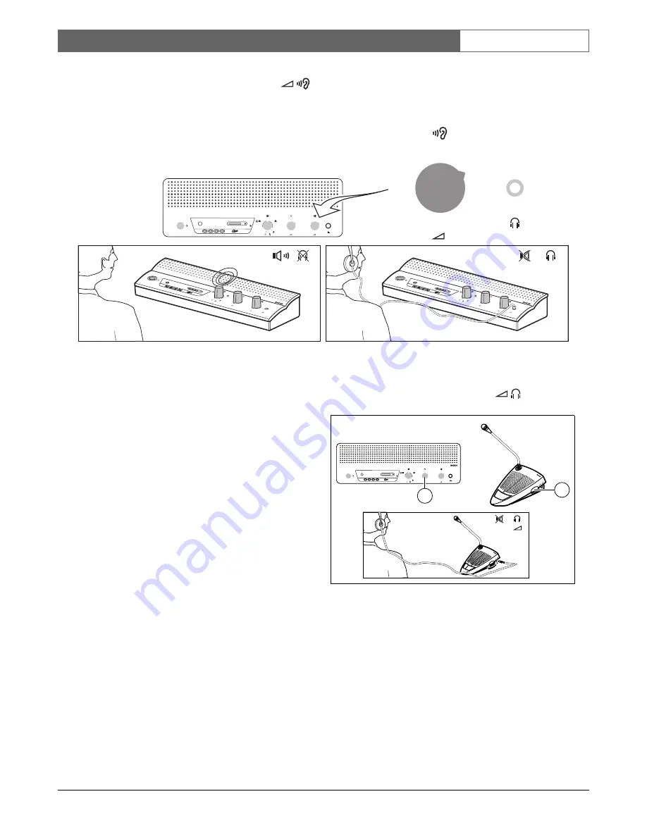
6.12 Monitoring volume control 

Use the built-in loudspeaker or a headphone to monitor 
the discussion. Adjust the volume using the monitoring 
volume control. The maximum level is controlled by 
the setting of the volume control for delegate and 
chairman units.

6.13 Using a headphone 

Figure 6.13

Use the rotary volume control (1) to adjust the volume 
of the headphones connected to the left and/or right 
side of the units. Inserting a headphone jack mutes the 
loudspeaker.
The maximum level depends on the setting of the 
volume control (2) on the CU.

Figure 6.12

CCS

800 ULTRO

0

1

2

3

4

5

6

7

8

9

10

0

1

2

3

4

5

6

7

8

9

10

4

3

2

1

1

2

3

4

CCS

800 ULTRO

0

1

2

3

4

5

6

7

8

9

10

0

1

2

3

4

5

6

7

8

9

10

4

3

2

1

1

2

3

4

0

1

2

3

4

5

6

7

8

9

10

0

1

2

3

4

5

6

7

8

9

10

0

1

2

3

4

5

6

7

8

9

10

4

3

2

1

1

2

3

4

CCS

800 ULTRO

0

1

2

3

4

5

6

7

8

9

10

0

1

2

3

4

5

6

7

8

9

10

4

3

2

1

1

2

3

4

CCS

800 ULTRO

1

2

Summary of Contents for CCS 800 Ultro

Page 1: ...CCS 800 Ultro Installation and Operating Manual Discussion System en ...

Page 2: ......

Page 3: ...e and chairman units 11 6 2 Using the microphone button of the delegate unit 11 6 3 Using the microphone button of the chairman unit 12 6 4 Using the priority button 12 6 5 Priority mode settings in chairman unit 12 6 6 Open mode 13 6 7 Open mode with auto switch off 13 6 8 Override mode 14 6 9 Chairman only mode 14 6 10 Volume control of the delegate and chairman units 15 6 11 Using Digital Acous...

Page 4: ...Bosch Security Systems B V 2007 08 CCS 800 Ultro Installation and Operating Manual en 4 ...

Page 5: ...oustic Feedback Suppression the loudspeaker volume can be increased significantly before feedback appears Digital Acoustic Feedback Suppression is only available in CCS CUD CCS CURD A delegate unit enables participants to actively join in a discussion i e speaking and listening by means of a microphone controlled by an on off button and a built in loudspeaker or external headphone A chairman unit ...

Page 6: ...hairman units To each output a maximum of 25 units can be connected The maximum length of cable between the outputs of the CU and the last unit in the system is 100 m 328 ft 8 Microphone input with gain adjustment for external microphone The external microphone will be muted when the priority button on the chairman unit is pressed 9 Recorder input with gain control and recorder output connection 1...

Page 7: ...hrough connection to the next unit 6 2m flying lead connection cable with sturdy moulded 7 pole circular male connector for connection to the previous unit or CU 7 Rotary volume control for headphones only 8 Microphone ON OFF push button 9 Chairman Priority button When pressed emits chime tone overrules mutes all active microphones of delegate units in the system and keeps the chairman s microphon...

Page 8: ...connection 5 4 Connecting an external microphone Figure 5 4 Put the external microphone 2 connector in the microphone input of the CU 1 Adjust the sensitivity by use of the gain control 3 Use only microphones with balanced output The microphone input provides a 12V phantom power supply Figure 5 2 max 6 x 25 units CCS 800 ULTRO 0 1 2 3 4 5 6 7 8 9 10 0 1 2 3 4 5 6 7 8 9 10 4 3 2 1 1 2 3 4 CCS 800 U...

Page 9: ...e gain control 3 to adjust the sensitivity of the recorder input of the CU 5 7 Connecting a PA system or other external equipment Figure 5 7 Connect a PA system 3 or other devices 2 to the in and output of the CU 1 Connect audio sources to the line input a PA amplifier or other sound processing devices to the line output 5 8 Connecting a telephone coupler Figure 5 8 Gain Gain 100 240 V Trunk in ou...

Page 10: ...n input and output of the CU 1 Switch 3 must be in position 1 loop through if the insertion input output is not used 5 10 Mains connection Figure 5 10 Use the supplied mains cord set 5 to connect the CU 1 to a protective earthed mains socket 2 Press the on off switch 3 to power up the system the display 4 will be lit 5 11 Connecting a USB cable Use the optional USB cable to connect the CU 1 to a P...

Page 11: ...dicators and LEDs of the delegate and chairman units must lit if properly connected 6 2 Using the microphone button of the delegate unit Depending on the position of the microphone mode switch on the CU pressing the microphone button on a delegate unit will activate the delegate microphone Pressing again switches the microphone off 4 3 2 1 1 2 3 4 0 1 2 3 4 5 6 7 8 9 10 0 1 2 3 4 5 6 7 8 9 10 4 3 ...

Page 12: ... B may be indicated by a chime tone and will deactivate all active delegate units A and activates the chairman microphone Release of the button will either leave the delegate units deactivated or activates them again depending on priority mode settings 6 5 Priority mode settings in chairman unit Figure 6 5 Remove the cable relief bracket 1 to set the chime and microphone switches in the required p...

Page 13: ... which can be activated by the delegates themselves at the same time If the speaker is silent for approximately 30 sec the active microphone switches off automatically Note Chairmen can always switch on and off their microphones and are not included in the max number Figure 6 6 4 3 2 1 1 2 3 4 1 4 1 4 0 1 2 3 4 5 6 7 8 9 10 0 1 2 3 4 5 6 7 8 9 10 4 3 2 1 1 2 3 4 CCS 800 ULTRO Figure 6 7 1 4 1 4 4 ...

Page 14: ...nly one delegate microphone is active at the same time Chairman microphones can always be switched on 6 9 Chairman only mode Figure 6 9 Only the chairman units B can be activated Delegates A can not switch on their microphone Figure 6 8 A A A B 4 3 2 1 1 2 3 4 B 0 1 2 3 4 5 6 7 8 9 10 0 1 2 3 4 5 6 7 8 9 10 4 3 2 1 1 2 3 4 CCS 800 ULTRO 4 3 2 1 1 2 3 4 A B 0 1 2 3 4 5 6 7 8 9 10 0 1 2 3 4 5 6 7 8 ...

Page 15: ...dspeaker volume to the required level but increasing the volume level more than 2 or 3 steps is not recommended Figure 6 10 0 1 2 3 4 5 6 7 8 9 10 2 1 1 0 1 2 3 4 5 6 7 8 9 10 0 1 2 3 4 5 6 7 8 9 10 2 0 1 2 3 4 5 6 7 8 9 10 0 1 2 3 4 5 6 7 8 9 10 4 3 2 1 1 2 3 4 CCS 800 ULTRO Gain Gain 100 240 V Trunk in out Recorder Line Telephone Insertion Digital Acoustic Feedback Suppression Microphone In Out ...

Page 16: ...the rotary volume control 1 to adjust the volume of the headphones connected to the left and or right side of the units Inserting a headphone jack mutes the loudspeaker The maximum level depends on the setting of the volume control 2 on the CU Figure 6 12 CCS 800 ULTRO 0 1 2 3 4 5 6 7 8 9 10 0 1 2 3 4 5 6 7 8 9 10 4 3 2 1 1 2 3 4 CCS 800 ULTRO 0 1 2 3 4 5 6 7 8 9 10 0 1 2 3 4 5 6 7 8 9 10 4 3 2 1 ...

Page 17: ...ll Recorded speech is saved on an SD card which is inserted into the top of the unit see following figure or saved internally After recording the SD card can be removed or the recorded speech can be downloaded to a PC by connecting a USB cable to the back of the CCS 800 Ultro Central Unit The MP3 recorder has a card exchange feature that allows the user to exchange the SD card during conversation ...

Page 18: ...nt of used free memory In pre listen mode and playback mode shows how much of the file has been played 6 Icons The space underneath the Progress and separator line is reserved for icons Various icons are used during recording pre listening and playback The icons vary according to the mode selected for more information see section 7 3 through section 7 5 7 Time Shows the time in hours minutes and s...

Page 19: ...ime Indicates that the time set up screen is selected Bit rate Indicates that the bit rate set up screen is selected Microphone recording Unit will only record if one or more microphones are active Constant recording Unit will constantly record one or more microphones do not have to be active Confirm delete Confirms file to be deleted Delete file Permanently deletes selected file Cancel delete Can...

Page 20: ...t the date and time as follows 1 Press the change mode button 1 to select the set up mode When selected the set up icon should be shown in the top right hand corner of the display see following figure Figure 7 3 Set up screen for date 2 Press the up or down button 4 or 5 to change the value year number and then press the select button 2 to select the next value to change 3 Set the date year month ...

Page 21: ...e down button to switch between constant recording or record when one or more microphones are active see table 7 2 2 Press the select button to select the next value to change see following section 7 3 6 Set internal external recording options 1 Press the down button to switch between record to the SD card or record to the internal memory see table 7 2 2 Press the change mode button 1 to exit the ...

Page 22: ... recording session New file Creates a new file during recording recording continues but the data is saved under a new file name The time counter on the display is also reset Change card Allows the user to change the SD card during recording see section 7 4 3 Change card timer Graphically shows the user how many seconds are remaining before the new card must be inserted Hourglass Icon will flash at...

Page 23: ...e short beeps will be played through the monitor loudspeaker This is to warn the operator to change the card If the card is not changed within 5 minutes a long beep will be played through the monitor loudspeaker at 0 minutes and the card exchange function will automatically start Change the card as follows 1 Press the change card button 5 The change card timer see table 7 3 will then be shown in t...

Page 24: ...r of the display Start Starts the pre listen or playback session depending on mode selected The first file in the list will be played As soon as this file has been played the next valid file will start Pause Pauses the pre listen or playback session depending on the mode selected When pre listen or playback has been paused the start icon will appear and start to flash Press the start button to con...

Page 25: ...ending on the mode selected 2 Press the start button 2 to pre listen to or playback files The MP3 tag is shown on the display If there is no MP3 tag the filename is shown instead 3 During pre listening or playback you can switch between pre listen and playback by press ing the change mode button 1 press the pause button to temporarily halt play back press the stop button to stop pre listening or p...

Page 26: ...k Suppression Possible cause Too close to microphone units when using open headphones Solution Increase the distance between headphone and microphone or disconnect headphones when not in use If available switch on Digital Acoustic Feedback Suppression Part of system not working Possible cause Interrupted trunk line cabling Solution Check the trunk line cabling connections between the units and the...

Page 27: ...ger than 2 GB are not supported Hourglass flashes for a long time after inserting the SD Card Possible cause The SD card is almost full Solution Remove old files recordings Format the SD card Possible cause The SD card is too slow Solution Use a faster SD card Recorded files missing on SD card Possible cause The SD card was removed during recording Solution Always stop recording before removing SD...

Page 28: ...ustment 0 20 dB Input impedance 47 kΩ for L and R channel Output level 20 dBV 5 dBV nominal maximum Output impedance 500 Ω External microphone input balanced Input sensitivity 56 dBV 6 dBV via included adapter Input sensitivity adjustment 6 dB 6 dB Phantom supply 12V 1V 2 x 680 Ω 2 Phantom supply is not available when using the included adapter Monitor loudspeaker Output level at 0 5 m 72 dB SPL 8...

Page 29: ...equency response 125 Hz 12 5 kHz tolerances acc to IEC 914 standard Total harmonic distortion at overload at nominal input level 85 dB SPL 0 5 at max input level 110 dB SPL 3 9 2 Mechanical Data 9 2 1 Control and Power Supply Unit Mounting free standing on a table top or mounted in a 19 rack requires 3HU Height Units with bracket set LBB 3311 00 Information about how to make the necessary brackets...

Page 30: ... 3 3 Transport AV18 Q0681 9 3 2Equipment Range Control and power supply unit CCS CU CCS CUD with Digital Acoustic Feedback Suppression CCS CUR with recording CCS CURD with recording and Digital Acoustic Feedback Sup pression 19 rack mounting set LBB 3311 00 Bracket for flush mounting can be made locally according to the illustration in 9 Appendix Delegate unit s LBB 3330 00 LBB 3330 50 with long m...

Page 31: ...crophone XLR B 1 GND 0V phantom supply 2 Signal 12V phantom supply 3 Signal 12V phantom supply phantom supply acc to DIN45596 10 1 3CINCH Connector C 1 Signal 2 Screen 10 1 4Mains Connector D 1 Mains 2 Earth 3 Mains Figure 10 1 CCS 800 ULTRO 0 1 2 3 4 5 6 7 8 9 10 0 1 2 3 4 5 6 7 8 9 10 4 3 2 1 1 2 3 4 Gain Gain 100 240 V Trunk in out Recorder Line Telephone Insertion Microphone In Out 6 1 4 2 5 3...

Page 32: ...bove the CU to have sufficient space for cable connections Mounted into a table using the flush mount bracket On a table Therefore drill four holes in the table and fasten the CU with four M3 screws B The delegate and chairman units can only be attached on a table Therefore drill two holes in the table and fasten the unit with two M3 screws A Figure 10 3 1 6 4 2 5 3 7 3 1 6 5 2 4 7 Yellow Drain Sh...

Page 33: ...t for Flush Mounting The drawing below gives the necessary information how to make a bracket for flush mounting the CU into a table Figure 10 5 4x 0 5 0 342 5 59 3 421 328 5 362 49 5 7 175 3 7 2x 4 6 2x 2 5 6X 6 95 8 135 90 234 5 29 5 64 47 8 50 3 130 20 52 461 ø8 6 4x 0 5 2 0 2 0 5 0 4 0 5 0 R 2 4x ...

Page 34: ...Bosch Security Systems B V 2007 08 CCS 800 Ultro Installation and Operating Manual en 34 ...

Page 35: ......

Page 36: ... Bosch Security Systems B V Data subject to change without notice 2007 08 For more information visit www boschsecurity com ...

Reviews: