English - 3
1
7
• F016 L70 348 • TMS • 08.09.05
Charging Procedure
The charging procedure starts as soon as the mains
plug is plugged into the socket and the battery
13
is
inserted into the charging compartment
16
.
Due to the intelligent charging method, the charging
condition of the battery is automatically detected and
the battery is charged depending on battery temper-
ature and voltage.
This gives longer life to the battery and always
leaves it fully charged when kept in the charger for
storage.
Control of the charging procedure is indicated via
the charge control LED
14
:
Rapid charging
The rapid-charging procedure is in-
dicated by
flashing
of the charge
control LED
14
.
The battery is fully charged as soon as the LED
4
switches from flashing to being lit continuously. Af-
terwards the battery can be removed for immediate
use.
It is recommended not to remove the battery until the
battery is fully charged.
☞
The rapid-charging procedure is possible only
when the temperature of the battery is be-
tween 0 °C and 45 °C.
Trickle charging
The trickle-charging procedure is in-
dicated by
continuous lighting
of
the LED
4
.
With the battery fully charged, the charger immedi-
ately switches to trickle-charge mode. This equal-
izes the natural running-down of the battery again.
Charging Advice
With continuous or several repetitive charging cy-
cles without interruption, the charger can warm up.
This is not harmful and does not indicate a technical
defect of the unit.
A battery that is new or has not been used for a
longer period does not develop its full capacity until
after approximately 5 charging/discharging cycles.
A significantly reduced working period after charging
indicates that the batteries are worn out and must be
replaced.
Do not connect the battery before product
is completely assembled.
Ensure product is assemble in the following or-
der:
Mounting the Cutting Guard
Place the cutting guard
10
on the trimmer head
8
.
➊
Hook the guard onto trimmer head and push until
secure fitting.
➋
Push rear of guard until secure (click).
Mounting the Wheels (ART 26/2600 ACCUTRIM
only)
Fit the wheels
11
onto the shaft
6
.
Fit the bolt
19
and the wingnut
18
.
Note:
The position of the wheels can be adjusted by
loosening the wingnut
18
and moving to the desired
position.
The wheels can be moved up and down the
shaft
6
depending on the height of cut required.
Fitting Cutting Disc/Fitting Blade
Press cutting disc
20
onto drive adaptor as
shown (click).
Fit the blade, place the blade
22
over the
pivot
21
and pull outwards until it snaps into place.
For Your Safety
Warning! Switch off, remove battery from ma-
chine before adjusting or cleaning.
The blade continues to rotate for a few sec-
onds after the trimmer is switched off.
Caution – do not touch rotating blade.
Assembly
A
B1
B2
B3
C
D
F016 L70 348 - GB Seite 3 Donnerstag, 10. November 2005 10:11 10
Summary of Contents for Art Accutrim
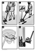
Page 2: ...2 F016 L70 348 05 09 360 1 2 3 4 6 10 13 17 5 8 9 11 12 7 14 15 16 ...
Page 3: ...3 F016 L70 348 05 09 C L I C K A B1 B2 B3 10 8 6 11 11 18 18 19 ...
Page 4: ...4 F016 L70 348 05 09 E F C D 5 3 4 6 22 20 20 21 ...
Page 5: ...5 F016 L70 348 05 09 G 90 H J I 12 6 11 18 6 6 5 7 12 6 ...


