


l
T
[mm]
b [mm]
160
160
225
240
160
240
320
240
65
10
10
165
X [mm]
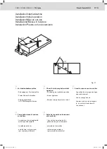
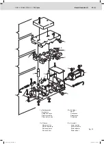
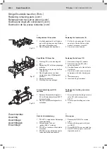
Fig. 10
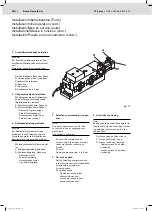
b
WT
l
WT
l
WT
X
VE1
S1
VE2
S3
S2
BG I
b
WT
l
WT
l
WT
X
VE1
S1
VE2
S3
S2
BG II
16/
32
Bosch Rexroth AG
TS 2
plus
|
3 842 523 895/2015-02
Montage (Zubehör), WT-Durchlaufsteuerung
Assembly (accessories), WT pass-through control
Montage (accessoires), commande de passage du WT
Montaggio (accessori), controllo del passaggio del WT
Montaje (accesorios), comando de pasaje de WT
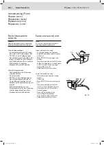
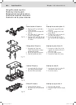
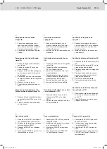
3. Teile zur WT-Durchlaufsteuerung ent-
sprechend Abbildungen und Tabelle
montieren:
Vereinzeler VE1 und VE2 (nach
separater Montageanleitung
3 842 512 700)
Näherungsschalter S1, S2 und S3
mit Schalterhalter SH 2/UV bzw.
SH 2/S
Minimalen Abstand X beachten!
3. Assemble the parts for the WT pass-
through control according to the
fi gures and table:
Stop gates VE1 and VE2 (accor-
ding to a separate assembly manual
3 842 512 700)
Proximity switches S1, S2 and S3
with switch brackets SH 2/UV or
SH 2/S, respectively
Note minimal distance X!
3. Monter les pièces pour la commande
de passage du WT en fonction des
illustrations et des tableaux :
Séparateurs VE1 et VE2 (d’après
les instructions de montage à part
3 842 512 700)
Détecteurs de proximité S1, S2
et S3 avec support d’interrupteur
SH 2/UV ou SH 2/S
Respecter l’écart minimal X!
3. Montare i componenti del controllo
del WT in base alle fi gure e alla
tabella:
Singolarizzatore VE1 e VE2 (secon-
do le istruzioni di montaggio a parte
3 842 512 700)
Gli interr. di prossimità S1, S2 e
S3 col supporto SH 2/UV ovvero
SH 2/S
Mantenere la distanza minima X !
3. Montar las piezas para el comando de
pasaje de WT según las fi guras y la
tabla:
Separadores VE1 y VE2 (según
instrucción de montaje separada
3 842 512 700)
Interruptores de aproximación S1, S2 y
S3 con soporte de interruptor
SH 2/UV o bien SH 2/S
¡Tener en cuenta la distancia mínima X!
523895_2015_02.indd 16
523895_2015_02.indd 16
19.02.2015 13:17:55
19.02.2015 13:17:55


