


1 689 989 325
2018-06-08
|
Robert Bosch GmbH
Operation | 0 986 613 670 | 13
en
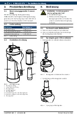
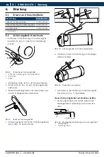
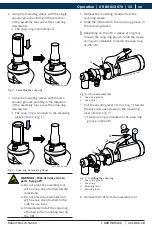
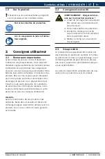
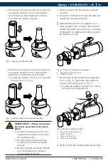
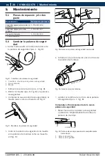
3.
Using the mounting sleeve with the single
annular groove pointing in the direction
of the assembly tool, press the snap ring
downwards.
The snap ring is spread apart.
4511001-14_shd
Fig. 4: Spreading the snap ring
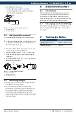
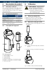
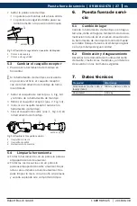
4.
Using the mounting sleeve with the two
annular grooves pointing in the direction
of the assembly tool, press the snap ring
downwards.
The snap ring is clamped to the receiving
sleeve (item 2, Fig. 1).
4511001-15_shd
Fig. 5: Snap ring on receiving sleeve
WARNING - Risk of injury due to
parts flying off!
Do not point the assembly tool
with a snap ring attached toward
individuals.
Do not place the assembly tool
with a snap ring attached to the
side for use later.
Immediately install the snap ring
attached to the mounting tool on
the CRI.
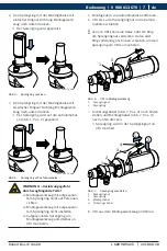
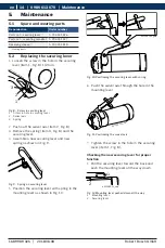
5.
Remove the mounting mandrel from the
receiving sleeve.
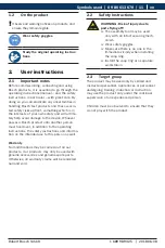
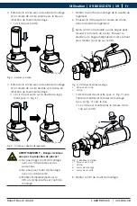
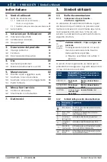
6.
Slide the CRI down to the snap ring groove in
the receiving sleeve.
i
Depending on the CRI, a sleeve or ring may
conceal the snap ring groove. Slide the sleeve
or ring up completely to install the snap ring
on the CRI.
1
2
4511001_16_shd
Fig. 6: CRI in assembly tool
1 Snap ring groove
2 Snap ring
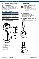
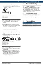
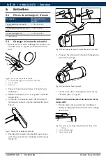
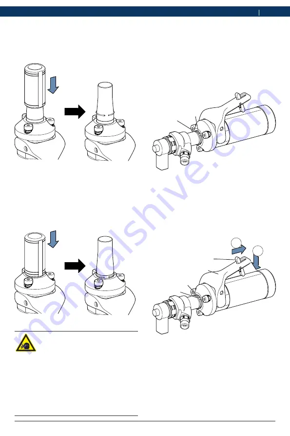
7.
Pull the securing lever (item 4, Fig. 7) toward
the back and push down on the mounting
lever (item 3, Fig. 7).
The snap ring is installed in the snap ring
groove on the CRI.
4
3
2.
1.
2
1
4511001-17_shd
Fig. 7: Installing the snap ring
1 Snap ring groove
2 Snap ring
3 Mounting lever
4 Securing lever
8.
Remove the CRI from the assembly tool.


