


EN
15
Installation
www.bora.com
(12)
10 ... 40
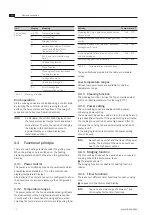
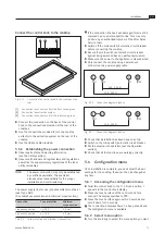
Fig. 5.6
Surface mounting cut-out
Cut-out dimensions when installing cooktops or cooktops
and the cooktop extractor next to each other:
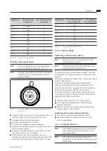
Cooktops/cooktop extractor
A in mm
B in mm
1/0
374
346
2/0
745
717
3/0
1116
1088
1/1
485
457
2/1
856
828
3/2
1338
1310
4/2
1709
1681
Tab. 5.2 Cut-out dimensions
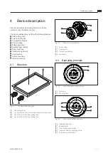
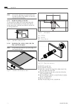
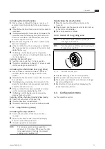
5.5 Installing the cooktop
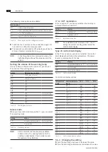
INFO
Clearance of one millimetre should be planned
between the built-in appliances.
INFO
A clearance of two millimetres should be
planned around the built-in appliances.
INFO
A mounting rail must always be fitted between
adjacent cooktops (available as an accessory).
INFO
Alternatively, the cooktop can be fitted rotated
about 180°.
Q
Q
Cross bars on the kitchen unit in the area of the
worktop cut-out may need to be removed.
Q
Q
The drawers and/or shelves in the floor unit must be
removable for maintenance and cleaning purposes.
X
X
Make sure that the area below the cooktop is
sufficiently ventilated.
X
X
Please note the worktop overhang x when creating
the worktop cut-out. Applies to flush installation and
surface mounting.
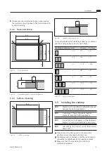
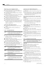
5.4.2 Flush installation
A ±2
B ±2
544 ±2
≤ R5
≤ R5
≥ 74
516 ±2
≥ 700
Fig. 5.3
Flush installation
7
14
10 ... 40
Fig. 5.4
Groove dimensions for flush installation
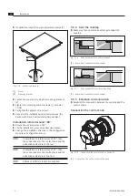
5.4.3 Surface mounting
B ±2
≤ R5
≥ 74
516 ±2
≥ 700
Fig. 5.5
Surface mounting
Summary of Contents for PKT11
Page 31: ......