THT-100
18
Boon Edam Inc.
402 McKinney Parkway
Version: Rev A6 10/28//2011
Tel. 910-814-3800 fax 910-814-3899
Issue: THT-100-IMM-USA
Heel guards*
The bottom rotor arms of the THT-100 can be fitted with an optional heel guard protector to
reduce direct contact of heels with the rotor arms. If a unit is pushed against a person’s foot or
heel the foam rubber protector will reduce the impact.
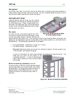
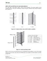
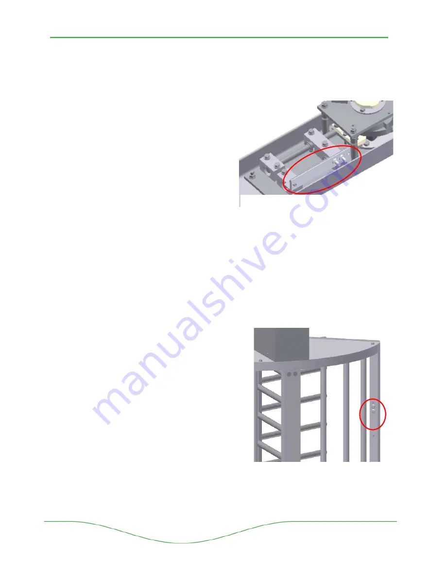
Heating Element Strips*
Optional heating element strips can be ordered
and applied to the internal top channel mechanism
for cold climate use. Power requirements (110-
220 VAC) vary depending upon the model ordered
and are to be connected separately from the main
control system, by others.
Fire alarm
For units tied into a fire alarm system, The THT-
100 can be configured to work accordingly. Keep
in mind that power failure functions override fire
alarm functions (reference 4.4.3). The Fire Alarm inputs found inside the Main Control Box are
directional, and dependent upon the configuration of the locking system (e.g., Fail Lock Exit or
Fail Safe Exit). The following configurations are available:
•
Fail Lock/Fail Safe – Under Fire, it is free out, no entry
•
Fail Safe/Fail Safe – Free Entry and Exit
Fail Lock
: Will release when the fire alarm is activated, however, if mains power is lost,
it will only open upon keyswitch bypass.
In case of a fire alarm, the rotor arms will allow free passage through the barrier. The
LED’s will turn green for free egress in the
configured direction. In case of simultaneous
power failure, reference 4.4.3 for Power Failure
functionality.
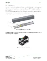
Electric Override Key Switch(es)
(optional)
The secure side of the THT-100 incorporates electric
override keyswitches into the back side of the shield
assembly post. The keyswitches allow the owner to
select functions of Card Read In/Free In or Card
Out/Free Out when the respective key switch is
activated.
Figure 4-6. Electric Override Key Switches
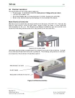
Figure 4-5. Heating Element Strip
(110-220VAC by others)

