


Hydraulics
Mito
QTH12 English
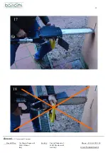
17
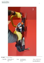
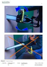
Do not force the bar, during cutting, to bending
effort
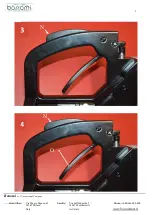
3
3
)
)
C
C
h
h
e
e
c
c
k
k
s
s
b
b
e
e
f
f
o
o
r
r
e
e
o
o
p
p
e
e
r
r
a
a
t
t
i
i
n
n
g
g
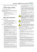
3.1) Connection to a water supply
The chainsaw is equipped with a water inlet system (figure
8. Connect the chainsaw to a water supply using this system
following those steps:
Connect the water hose (O) to the quick hose
connector (P); Not present
Make sure there is no water leakage;
the maximum pressure of incoming water is 4 bar
(58 PSI);
use just clean water;
4
4
)
)
B
B
a
a
r
r
,
,
c
c
h
h
a
a
i
i
n
n
a
a
n
n
d
d
S
S
p
p
r
r
o
o
c
c
k
k
e
e
t
t
4.1) How to use the bar
the bar (B) needs to be periodically flipped over in
order to wear out eavenly on both sides;
the bar wears out. Usually you need to replace it
every 2 to 3 times you replace a chain;
a correct chain (A) tension allows a longer bar life. See
paragraph
4.2
and image U,V,Z page 10
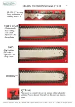
4.2) How to use the chain. WARNING
Chains usage lead to chain stretching;
An optimal chain tension reduces chain and bar
wear and increases productivity and safety.
Check chain tension before use and stop
periodically during operation to make sure the chain
tension is correct;
An excessive tension leads to higher friction,
reducing cutting performance and increasing bar
and chain wearing;
A loose chain reduces cutting performance and can
lead to the chain to disengage from the bar;
Follow steps in paragraph
4.3) Mounting and
replacing bar and chain
to set the correct chain
tension;
see
also
movie
on:
https://www.youtube.com/watch?v=pX1tBLgFTQU&
t=4s
Check the chain more frequently when the chain is
new since new chains have higher chain stretching.
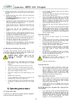
your hydraulic chainsaw machine is equipped with
a rapid tensioning system called Quick Tensioning
which greatly facilitates the chain tensioning
manoeuvres and thanks to this the chain can work
with the correct tension without the aid of
particularly complicated mechanical manoeuvres,
simply by operating the knob shown in figure 1, T
Pay close attention to the use of this easy and
immediate tensioning system and perform tension
tests before cutting in order to get used to the
tension system
Never perform the tension by turning the knob
shown in figure 1, T during the cutting
The tensioning of the chain must be carried out with
the guide bar pulled out of the cut and with the
chain stopped. Once the ideal tension has been
reached, as described in the following point 4.3
activate the hydraulic saw motion to check if the
tension reached is maintained. If the tension is
optimal, as described in point 4.3, you can continue
with the cutting operations.
The correct maneuver is: Remove the guide bar
from the cut, stop the engine visually check the
conditions of extension of the chain with respect to
the guide bar, (the correct chain tension is shown in
figures U, V, Z in page 10) operate, if necessary,
the tensioning operation of the chain by acting on
the knob of fig. 1, T.
Since the operation is very simple, it is
recommended to avoid the over tension of the
chain, the excessive tension of the chain is not
recommended before starting the cut and can
reduce the chain life
The equipment allows tensioning and give up the
chain with a simple screwing or unscrewing
operation of the indicated knob,
it is therefore the
operator's
responsibility
to
realize
that
excessive tension can cause damage to the
equipment as well as to people and damage the
chain by cracking.
We invite any operators to take good knowledge of
the use of this easy system that on the one hand is
very effective in terms of operator fatigue and
cutting times on the other hand if used with abuse
can induce the chain to work in conditions of
overload and permanently damaging it,
thus
creating a dangerous condition.
4.3) Mounting and replacing bar and chain
Before mounting or replacing the bar (B) or the
chain (A) make sure the chainsaw is unplugged (M)
and the power pack is switch off. Do this operation
in a safe place, use protective gloves and place the
product on a stable
surface.
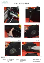
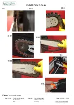
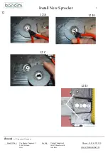
Installing Chain (A) See figure 10, page 10, 1, and follow
these
steps:
or
link
to
the
movie
https://www.youtube.com/watch?v=pX1tBLgFTQU&t=4s
1.
Unscrew and remove the 2 side cover screw (11/A)
2.
Remove the cover (11/B);
3.
loosen the 11/A nut on the back of the machine the guide
bar will be released and can slide back and forth and is
free to change,
4.
Using the, T tension knob. Return the sprocket to the
initial position from 11C to11C1, page 7
5.
Positioning the guide bar towards the sprocket 10/D in
order to create the necessary space for inserting the
chain,
6.
Easily extract the old chain,
7.
Insert the new chain on the guide bar 10/A and wind the
chain around the 10/B guide bar head bearing, to have
the chain saving at the back of the sprocket 10/G,
8.
Install the chain on the sprocket proper position 10/C,
please note
the reverse chain made specifically for this
machine has a sense of cutting, see fig Y page 10, make
sure not to install the chain in the opposite direction,
9.
If you install the chain in the wrong direction
compromises the functionality of the same as well as
damage it irreparably,
10.
Repeat reverse step from point 4.3 to 4.1 to fix not
permanently the cover.
11.
Pull the guide bar by positioning the chain in a manual
tension position, see page 8, Fig.10G to 10H and than
Screw and fix the 2 nut 11/A on the back of the machine
body and secure the guide bar to the machine body fig
10/I


