background image

M3628ACF


1.4. 

S

YMBOL 

C

ONVENTIONS 

U

SED IN THIS 

M

ANUAL AND ON 

E

QUIPMENT


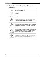
Earth Ground or Protective Earth 


AC Voltage 


DC Voltage 


DANGER! 

DANGER: Electrical hazard - Identifies a statement that indicates 
a shock or electrocution hazard that must be avoided. 


DANGER! 

DANGER: Identifies information about practices or circumstances 
that can lead to personal injury or death, property damage, or 
economic loss. 


CAUTION! 

CAUTION: Identifies information about practices or circumstances 
that can lead to property damage, or economic loss. Attentions 
help you identify a potential hazard, avoid a hazard, and 
recognize the consequences. 


CAUTION! 

CAUTION: Heat or burn hazard - Identifies a statement regarding 
heat production or a burn hazard that should be avoided. 


Summary of Contents for M3628ACF

Page 1: ...Web www bonitron com Tel 615 244 2825 Email info bonitron com Model M3628ACF Automatic Capacitor Former Customer Reference Manual ...

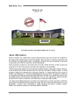
Page 2: ...design develop and manufacture the quality industrial electronic systems demanded in today s market A strong academic background supported by continuing education is complemented by many years of hands on field experience A clear advantage Bonitron has over many competitors is combined on site engineering labs and manufacturing facilities which allows the engineering team to have immediate access ...

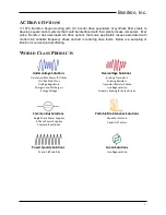
Page 3: ...Below is a sampling of Bonitron s current product offering WORLD CLASS PRODUCTS Undervoltage Solutions Overvoltage Solutions Uninterruptible Power for Drives DC Bus Ride Thru Voltage Regulators Chargers and Dischargers Energy Storage Braking Transistors Braking Resistors Transistor Resistor Combo Line Regeneration Dynamic Braking for Servo Drives Common Bus Solutions Portable Maintenance Solutions...

Page 4: ...M3628ACF 4 This page intentionally left blank ...

Page 5: ...2 4 General Precautions and Safety Warnings 12 3 INSTALLATION INSTRUCTIONS 13 3 1 Environment 13 3 2 Wiring and Customer Connections 13 3 2 1 Power Wiring 13 Figure 3 1 M3628ACF 13 3 2 2 Source Considerations 13 4 OPERATION 15 4 1 Functional Description 15 4 2 Features 16 4 2 1 Hardware 16 4 2 2 Screens Menu Navigation 17 Figure 4 2 M3628ACF Charging Profile 17 Figure 4 3 M3628ACF Interface Screen...

Page 6: ...M3628ACF 6 This page intentionally left blank ...

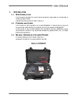
Page 7: ...for the model M3628ACF It will provide the user with the necessary information to successfully connect and operate the M3628ACF In the event of any conflict between this document and any publication and or documentation related to any associated hardware capacitor bank etc the latter shall have precedence 1 3 MANUAL VERSION AND CHANGE RECORD The initial release for this module is Rev 00a Updates t...

Page 8: ...ntifies information about practices or circumstances that can lead to personal injury or death property damage or economic loss CAUTION CAUTION Identifies information about practices or circumstances that can lead to property damage or economic loss Attentions help you identify a potential hazard avoid a hazard and recognize the consequences CAUTION CAUTION Heat or burn hazard Identifies a stateme...

Page 9: ...or DC input is available along with separate float and equalization charge levels The charger is current limited and designed for use in integrated storage and backup systems but can also be used in bench or mobile systems KIT 3628T ULTRA CAPACITOR DISCHARGER Large capacitor banks store huge amounts of energy and can be a hazard when systems are shut down for system maintenance The KIT 3628T syste...

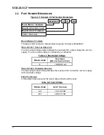
Page 10: ...voltage is indicated by a code letter Table 2 1 Max Output Voltage RATING CODE VOLTAGES DC VOLTAGE OUTPUT Y 1000VDC out MAX OUTPUT CURRENT RATING The max output current rating indicates the maximum DC current the unit can supply at its maximum voltage INPUT VOLTAGE A three digit code represents the input voltage that should be used Table 2 2 Input Voltage RATING CODE INPUT VOLTAGE 120 110 120 VAC ...

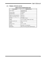
Page 11: ...tput Voltage 0 1000VDC Output Current 0 1ADC Maximum Load Capacitance 300 000uF Maximum Discharging Time 20 minutes Controls Six display soft keys Display Four line eighty character LCD 4x20 Unit Size H x W x D 22 0 x 13 9 x 9 0 Weight 49 lbs Storage Temp 20 C to 65 C Humidity Below 90 non condensing Atmosphere Free of corrosive gas and conductive dust ...

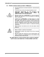
Page 12: ... POLARITY REVERSED CAN CAUSE DAMAGE TO YOUR EQUIPMENT AND POTENTIALLY CREATE A FIRE OR EXPLOSION HAZARD THREATENING LIVES ENSURE THAT THE POSITIVE AND NEGATIVE TERMINALS ON BOTH THE SOURCE AND LOAD ARE POSITIVELY IDENTIFIED AND CORRECTLY CONNECTED BEFORE OPERATION NEVER OPERATE THIS PRODUCT WITH THE ENCLOSURE COVER REMOVED DANGER NEVER ATTEMPT TO SERVICE THIS PRODUCT CERTAIN PARTS INSIDE THIS PROD...

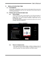
Page 13: ...Hz from the included standard C13 power cable The DC Output connectors supply DC voltage at the user selected level via a pair of banana connectors Output leads can be constructed as needed The unit should be powered ON before connecting to a load as the unit is in discharge mode when powered off Figure 3 1 M3628ACF 3 2 2 SOURCE CONSIDERATIONS Input voltage should not exceed 120VAC 240VAC or damag...

Page 14: ...M3628ACF 14 This page intentionally left blank ...

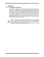
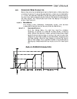
Page 15: ...he ACF will display a measurement of its capacitance Alternately the user may initiate a forming profile with defined current limits step voltages and hold times before the unit automatically discharges the load Figure 4 2 The Cancel button will act as an immediate discharge button in case of accidental overvoltage The unit automatically enters discharge mode when powered off NOTE If the non capac...

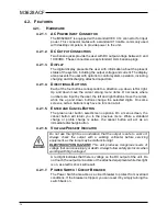
Page 16: ...the up and down buttons change the selected digits On some screens certain buttons may have no function at all 4 2 1 5 ENTER AND CANCEL BUTTON The green enter button selects menu options On a menu screen the cancel button will return you to the previous menu While a standard charge or profile charge is active the cancel button will act as an immediate discharge button 4 2 1 6 VOLTAGE PRESENT INDIC...

Page 17: ... menu Discharge Confirmation screen and previous measurement Results may be accessed from the Main Menu 4 2 2 1 1 CHARGING PROFILE From the Charge Menu the user may input the variables necessary to execute an automatic forming profile A forming profile charges the capacitor in steps each step a specified voltage apart When each step voltage is reached the load is held at that voltage for a specifi...

Page 18: ...ROFILE CHARGE CAP CONFIRM DISCHARGE NO YES DISCHARGING SET VOLTAGE MENU BASIC CHARGE START CHARGING SET CURRENT CONFIRM CHARGE YES NO SET VOLTAGE MENU PROFILE CHARGE SET FINAL HOLD TIME SET STEP VOLTAGE SET FINAL VOLTAGE SET CHARGE CURRENT SET STEP HOLD TIME START CHARGING CHARGE YES HOLD TIME SET FINAL SET FINAL VOLTAGE CHARGING SET CURRENT SET SET ...

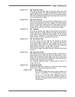
Page 19: ...4 SET STEP HOLD TIME From this screen the user may set the number of minutes each step voltage will be held The right and left buttons control which digit is presently being edited and the up and down buttons increment or decrement that digit Pressing Enter will exit this screen and save the hold time The maximum step time is 999 minutes or about 16 hours and 39 min 4 2 2 1 1 5 SET FINAL HOLD TIME...

Page 20: ...s screen displays the present output voltage and current It transitions to the Voltage screen 4 2 2 2 when the output voltage reaches the set point Charging may be aborted by pressing the Cancel button 4 2 2 1 3 DISCHARGE CONFIRM At this screen the user is asked to confirm their intent to discharge the capacitor bank If the user confirms the capacitor starts discharging until the load voltage reac...

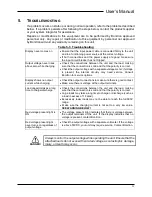
Page 21: ...al circuitry may need service Consult Bonitron for service options Display shows no output current while charging Check the output connections to make sure there is good contact Make sure there is voltage at the output terminals Load capacitor takes a long time to charge discharge Check the connections between the unit and the load making sure that the connection is solid and that the polarity is ...

Page 22: ...M3628ACF 22 This page intentionally left blank ...

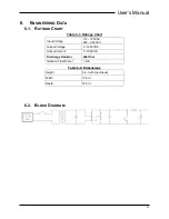
Page 23: ...able 6 1 Ratings Chart Input Voltage 110 120VAC 220 240VAC Output Voltage 0 1000VDC Output Current 0 1000mA Discharge Resistor 240 Ohm Isolation Transformer 1 kVA Table 6 2 Dimensions Height 9 in with top closed Width 13 9 in Depth 18 0 in 6 2 BLOCK DIAGRAM ...

Page 24: ...M3628ACF 24 This page intentionally left blank ...

Page 25: ... ensure that you are directly across the DC bus not attached through the braking circuit 4 Select Charging Profile from the main menu 5 Set the final voltage to the rated voltage of the capacitor bank 6 Set the step voltage to approximately 10 of the rated voltage of the capacitor 7 Set the charging current to its maximum setting unless counter indicated by the capacitor manufacturer 8 Set the ste...

Page 26: ...put into use as appropriate 13 If the bank is put into service test the capacitor bank periodically on a schedule recommended by the capacitor manufacturer Ensure that all tests are performed in a similar ambient temperature otherwise comparison between results may not be valid If over time the bank capacitance falls below the manufacturer recommended percentage of the original recorded capacitanc...

Page 27: ......

Page 28: ...D_M3528ACF_CMAN_VALL_00b 05 29 2018 521 Fairground Court Nashville TN 37211 USA Tel 615 244 2825 Fax 615 244 2833 Web www bonitron com Email info bonitron com ...

Reviews: