background image


AGL-STOV0-01SV0-05 

06/12 


35


10.4


Group Stop, SS 1 


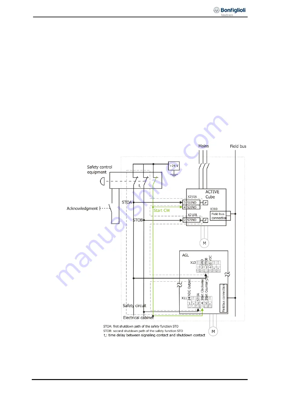
The application circuit shows a drive control system with PLC and safety module ac-

cording to EN ISO 13849-1 PL d and Category 3 or IEC 61508 SIL 2. A PLC performs 

the process control of the frequency inverter and can start the drive profiles via 

commands which are communicated through the field bus. 

If the protective device is actuated, e.g. emergency stop switch, the enable paths of 

the safety module are interrupted. At first, the travel signal “Clockwise” is reset. 
Then, the motors are decelerated in a controlled way. After a delay t

v

, the controller 

enable signal of the frequency inverters is interrupted via the disconnection of the 

control voltages from STOA and STOB and the integrated safe pulse block is acti-

vated. 

Via the field bus, the (non-safe) feedback is transmitted to the PLC indicating that the 

drives have stopped. Except for the terminals shown in the diagram, no further ter-
minals are required for connection. 

Note, that with high current demand a fuse leading to the safety contacts might be 

necessary according to the instructions of the safety device manufacturers. 

The external DC 24 V supply must be dimensioned accordingly, see chapter 


7.3.1. 

In group stop setups pulsed signals could lead to more frequent false trippings.  


Summary of Contents for Agile Series

Page 1: ...Agile Application manual Functional Safety...

Page 2: ......

Page 3: ...ding to the customer specific requirements made on the frequency inverter Quick Start Guide The Quick Start Guide describes the basic steps required for mechanical and electrical installation of the f...

Page 4: ...30 V 12 4 Information of Risk Analysis and Risk Assessment 13 5 General Description of Safety Function 14 5 1 Integrated Safety Function 14 5 2 Functional Safety 14 5 3 Classification the safety requi...

Page 5: ...C with error exclusion short circuit in the cabinet 29 10 2 SS1 according to Stop Category 1 30 10 2 1 SS1 Direct Stop 30 10 2 2 SS1 Direct Stop with error exclusion short circuit in the cabinet 31 10...

Page 6: ...ects connected with the use of the frequency inverter is described specific to the application If you need a copy of the documentation or additional information contact your local representative of BO...

Page 7: ...n death serious injury or material damage Caution Caution refers to an indirect threat Non compliance may result in personal or material damage Attention Attention refers to a possible operational beh...

Page 8: ...y inverters are electrical drive components intended for installation in industrial plants or machines Commissioning and start of operation is not allowed until it has been verified that the machine m...

Page 9: ...nstallation from all possible sources of electrical power Secure against reconnection Only the persons working on the installation may re commission the relevant part of the installation Verify there...

Page 10: ...be performed while the system is in operation 2 6 1 Operation with products from other manufacturers Please note that Bonfiglioli Vectron will not accept responsibility for compatibility with product...

Page 11: ...of the frequency inverter Resetting of an emergency stop must not result in uncontrolled starting of the drive The drive is started again when the function STO is no longer triggered In order to compl...

Page 12: ...requency inverter High voltage levels may be present at the motor Do not touch live terminals Permanent magnet synchronous motors PMSM must be operated only up to the synchronous speed PMSM cannot be...

Page 13: ...que Off the risk assessment must con sider the fact that the motor will coast to a standstill in the case of an error Depend ing on the application a mechanical brake may be required Responsibility Th...

Page 14: ...ent The integrated safety function Safe Torque Off of the AGL frequency inverter meets the following requirements according to EN 61800 5 2 up to safety integrity level SIL 2 according to DIN EN 61508...

Page 15: ...llsetzen nach EN 60204 1 Stopp Kategorie 1 Definitions according to EN 60204 1 Stop category 0 Stop by immediate disconnection of energy supply to the machine drive elements i e uncontrolled stop Stop...

Page 16: ...switches from above DC 15 V to less than DC 5 V Latest when falling below DC 5 V the response time begins and ends at the moment where torque can no longer be generated Fault Response time Time betwee...

Page 17: ...Level EN ISO 13849 1 d Kategorie EN ISO 13849 1 3 Amount of Processs interfaces Two 2 Design of Processs interface Two yellow marked spring terminals X11 3 and X13 3 inputs STOA und STOB Type of Proce...

Page 18: ...ce according to requirements of risk analysis Two yellow marked spring terminals X11 3 and X13 3 inputs STOA und STOB Type of Processs interface STO SPS Type 1 compatible according to IEC61131 2 Opera...

Page 19: ...s The Safe Torque Off can be limited to certain plant areas in this way Another advan tage is the fact that it is not necessary to wait until the frequency inverter has been charged and discharged Thu...

Page 20: ...Off Safe Torque Off can be achieved by Intentional triggering during operation in order to stop a drive and safely prevent restarting e g for maintenance work on a machine Triggering by actuation of...

Page 21: ...rotection device is actuated the control voltages are interrupted the energy supply to the motor is switched off Disconnec tion is effected at a delay according to chapter 6 2 If the function STO is t...

Page 22: ...e status changes to STO triggered and the output stage is inhibited In this state the monitoring function checks that during the next 5 seconds the second input is switched off If this has not been do...

Page 23: ...installed in electrical cabinets with high IP protection e g IP 54 If external forces act on the drive axis e g in the case of vertical axes sus pended loads or round axes with asymmetrical weight di...

Page 24: ...nsor signals that safety door is open is reset emergency stop unlocked safety door closed this alone shall not result in a restart of the drive Restart may only occur after the safety control device h...

Page 25: ...safety function at regular intervals The test intervals are to be determined according to the risk analysis However the check should be performed once every year at the latest 9 Requirements to be me...

Page 26: ...IL 2 When operating the emergency stop device with two stop channels both release paths paths STOA and STOB of the Agile frequency inverter are interrupted and the integrated safety function is trigge...

Page 27: ...IEC 61508 SIL 2 Safety control equipment with one enable path and interconnection line is implemented instead of safety con trol equipment with two enable paths Comply with the following conditions S...

Page 28: ...can start the drive profiles via commands If the protective device is actuated e g safety door open the release paths of the safety module are interrupted Through the interruption of the control volta...

Page 29: ...d Category 3 or IEC 61508 SIL 2 Safety control equipment with one enable path and interconnection line is implemented instead of safety control equipment with two enable paths Comply with the followin...

Page 30: ...avel command Clockwise is reset first After a delay tv the contacts on the safety switch interrupt the two enable paths STOA and STOB of the Agile frequency inverter and the integrated safety func tio...

Page 31: ...LC and safety module Safety control equipment with one enable path and interconnection line is implemented instead of safety control equipment with two enable paths Comply with the following condition...

Page 32: ...e g safety door open the release paths of the safety module are interrupted The PLC is triggered first that the safety function was actuated which then decele rates the motor by resetting the start co...

Page 33: ...d Category 3 or IEC 61508 SIL 2 Safety control equipment with one enable path and interconnection line is implemented instead of safety control equipment with two enable paths Comply with the followin...

Page 34: ...tacts on the safety switch interrupt the two enable paths STOA and STOB of the ACTIVE Cube frequency inverter and the integrated safety function is triggered by interrupting the inverter release The d...

Page 35: ...d in a controlled way After a delay tv the controller enable signal of the frequency inverters is interrupted via the disconnection of the control voltages from STOA and STOB and the integrated safe p...

Page 36: ...unction Installation EMC instructions in the operating instructions considered The DC 24 V supply was selected and installed based on the requirements of this manual The shield of the 24 V power suppl...

Page 37: ...according to EN ISO 13849 1 and SIL 2 SILCL 2 according to EN 62061 IEC 61508 EN 61800 5 2 erf llt The requirements of the manual have to be complied with 12 1 Characteristical Data The following dat...

Page 38: ...38 AGL STOV0 01SV0 05 06 12 14 Change index AGL STOV0 01SV0 05 First release in English language...

Page 39: ...cy switch off 11 Enforced dynamizing 23 Fault exclusion 23 FMEA 14 Information on Use 10 Installation 9 Requirements 23 Instruction manuals 6 Machinery Directive 13 Norm EN 60204 1 23 EN 61800 5 2 23...

Page 40: ...84 650 3577422 www bonfiglioli vn salesvn bonfiglioli com Bonfiglioli Australia 2 Cox Place Glendenning NSW 2761 Locked Bag 1000 Plumpton NSW 2761 Tel 61 2 8811 8000 Fax 61 2 9675 6605 www bonfigliol...

Page 41: ......

Page 42: ...aly tel 39 051 647 3111 fax 39 051 647 3126 bonfiglioli bonfiglioli com www bonfiglioli com Bonfiglioli has been designing and developing innovative and reliable power transmission and control solutio...

Reviews: