background image


31

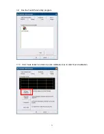
1.9  Run the Touch Panel utility program 


1.10    Click “tools folder” and click 4 points calibration box to start Touch Calibration. 


Summary of Contents for Xterra-POS

Page 1: ......

Page 2: ... could cause fire or electrical shock 9 If one of the following situations arises get the equipment checked by a service personnel a The power cord or plug is damaged b Liquid has penetrated into the equipment c The equipment has been exposed to moisture d The equipment does not work well or you can not get it work according to user s manual e The equipment has dropped and damaged 10 Do not leave ...

Page 3: ...f the publisher All products and trade names described within are mentioned for identification purpose only No affiliation with or endorsement of the manufacturer is made or implied Product names and brands appearing in this manual are registered trademarks of their respective companies The information published herein has been checked for accuracy as of publishing time No representation or warran...

Page 4: ...to correct the interference by one or more of the following measures Reorient or relocate the receiving antenna Increase the separation between the equipment and receiver Connect the equipment into an outlet on a circuit different from that to which the receiver is connected Consult the dealer or an experienced radio TV technician for help Shielded interface cables must be used in order to comply ...

Page 5: ... P8 3 Internal Layout P9 4 Pin Definition P10 12 5 Rear I O Interface P13 14 6 System Assembly Disassembly P15 17 6 1 MSR P15 17 6 2 HDD RAM P18 20 6 3 VFD LCM P21 22 6 4 2nd Display P23 26 7 Device Driver Installation P27 39 7 1 Resistive Type Touch Panel P27 32 7 2 MSR Dallas iBUTTON P33 39 8 BIOS Utility Setup P40 46 9 LCD Surface Cleaning P47 ...

Page 6: ...6 1 Packing List 1 1 Standard Accessories a b c d e x4 a System b Power Adapter c Power Cord d Driver Bank e Screw ...

Page 7: ...DIMM Supports 512MB 2GB VIA VT1708S 10 100 1000Mbps Base T Fast Ethernet 4 USB 1 1 2 0 DOM CF 2 5 SATA HDD SSD Award PnP BIOS 8Mb SPI ROM DC 12V 5A 60W Adaptor Power DC 12V 8 33A 100W Adaptor Power for DC out Fan less 373 W x 319 H x 348 D mm 0 C 40 C 20 C 60 C 20 80 non condensing 15 inch TFT Active Matrix Display 1024 768 Pixels 250 cd m2 5 wire Resistive 30 90 Item 1 USB ports 2 Power LED 3 Res...

Page 8: ... COM1 port 5V 12V selection 10 Lan port 11 USB ports 12 RJ11 port for Cash Drawer 13 PS 2 port 14 Kensington lock 15 Line out 16 COM3 port 5V 12V Selection 17 COM2 port 5V 12V selection 18 Parallel port 19 DC out option Item 21 VESA Mount Holes 100mm x 100mm 20 ...

Page 9: ...Connector for Power button USB 14 LVDS 5 COM4 COM5 SO DIMM 1 Speaker 2 Line out Battery IDE 3 Parallel 4 Jumper for COM Power selection 9 SATA power 13 Inverter CF 6 USB Pitch 2 0 8 CMOS jumper Mini PCIe option 10 DC out 7 Powered USB ...

Page 10: ...TA1 16 INIT Printer Initialize 4 PD2 Parallel Port DATA2 17 SLIN Printer Select Input 5 PD3 Parallel Port DATA3 18 GND Ground 6 PD4 Parallel Port DATA4 19 GND Ground 7 PD5 Parallel Port DATA5 20 GND Ground 8 PD6 Parallel Port DATA6 21 GND Ground 9 PD7 Parallel Port DATA7 22 GND Ground 10 ACK Printer Acknowledge 23 GND Ground 11 BUSY Printer Busy 24 GND Ground 12 PE Printer Paper End 25 GND Ground ...

Page 11: ...POWER 5VS 2 USB_DN USB Data 3 USB_DP USB Data 4 GND Ground 7 Powered USB J19 Pitch 2 0 reserved for Model AU3821 Pin NO Pin Name Description 1 POWER 5VSTBY 2 USB_DN USB Data 3 USB_DP USB Data 4 GND Ground 8 CMOS Jumper Clear CMOS data by moving jumper JBAT1 to 2 3 position and then back to 1 2 position Pin NO Pin Name Description 1 VCC 3 3V 2 RCT_RST RTC Reset 3 GND Ground 9 SATA power J5 Pin NO P...

Page 12: ...round 7 USB4_DN USB 4 Data 14 PWRTN Power button 13 Inverter CN2 Pin NO Pin Name Description 1 VCC 12V 2 GND Ground 3 NC NC 4 BKL_CTL Back Light Control 5 BKL_EN Back Light Enable Control 14 LVDS CN 1 Pin NO Pin Name Description Pin NO Pin Name Description 1 LCDVCC 3 3v 15 GND Ground 2 LCDVCC 3 3v 16 GND Ground 3 GND Ground 17 DATA0_N LVDS Output DATA0 4 GND Ground 18 DATA0_P LVDS Output DATA0 5 N...

Page 13: ...13 5 Rear I O Interface 1 COM RS232 port 2 Parallel port 3 VGA port 4 USB port ...

Page 14: ...14 5 PS 2 K B port 6 Lan port 7 RJ11 port for Cash drawer 8 DJ Jack 9 DC out option ...

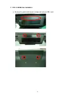
Page 15: ...5 6 Peripherals Installation 1 Magnetic Card Reader I button Installation a Loosen 1 screw and open MSR cover b The connector for MSR cable connecting is reserved c Cut off the edge of MSR cover by hand ...

Page 16: ...16 d Fasten the Magnetic Card Reader I button on the plate chassis with 2 screws e Connect the MSR cable ...

Page 17: ...17 f Fasten the plate chassis on panel cover with 3 screws g Fasten the MSR cover ...

Page 18: ...18 2 HDD Memory Installation a Loosen 4 screws and remove cable cover b Loosen 1 screw and remove the base cover ...

Page 19: ...19 c Fasten the HDD on HDD bracket with 4 screws d Connect SATA cable with HDD ...

Page 20: ...20 e Connect the SATA cable f Fasten the HDD bracket with 2 screws g Fasten the base cover with1 screw h Fasten the cable cover with 4 screws ...

Page 21: ...21 3 VFD LCM Module Installation a Remove the plate and loosen 4 screws and remove VFD cover ...

Page 22: ...22 b Connect VFD cable and fasten the VFD LCM module with 4 screws c Recover and fasten VFD cover with 4 screws the stick the plate as shown below d Stick the plate ...

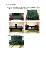
Page 23: ...23 4 2nd Diplay Installation a Loosen the cable cover with 4 screws Loosen 2 rubbers which near the I O ports on case base then fasten the 2 rubbers on cable cover b connect VGA and audio cables ...

Page 24: ...24 c Reeve the cables out of the tube of cable cover d Assemble the cable cover and fasten 4 screws e Fasten 2 screws on case base ...

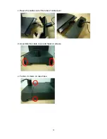
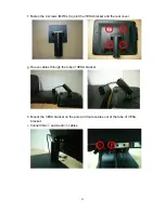
Page 25: ...ws M4 8L to joint the VESA bracket and the rear cover g Reeve cables through the tube of VESA bracket h Mount the VESA bracket on the pole and route cables out of the tube of VESA bracket i Connet VGA1 and Audio2 cables 1 2 ...

Page 26: ...26 j Manage the cables into the pole k Put the cable cover on the hinge of VESA bracket ...

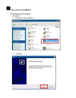
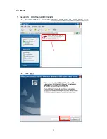
Page 27: ...27 7 Device Driver Installation 7 1 Resistive Type Touch Panel 1 Installation 1 1 Run Setup to start installation 1 2 Click Next ...

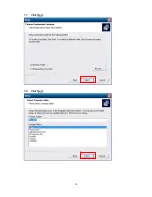
Page 28: ...28 1 3 Click Next 1 4 Select None and click Next ...

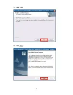
Page 29: ...29 1 5 Click OK 1 6 Click Next ...

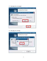
Page 30: ...30 1 7 Click Next 1 8 Click Next ...

Page 31: ...31 1 9 Run the Touch Panel utility program 1 10 Click tools folder and click 4 points calibration box to start Touch Calibration ...

Page 32: ...32 1 11 Follow the instruction to touch the four cross points 1 12 Calibration done ...

Page 33: ...33 7 2 MSR 1 Install OS POSReady2009 English 1 1 Driver Installation Execution CP210x_VCP_Win_XP_S2K3_Vista_7 exe 1 2 Click Next ...

Page 34: ...34 1 3 Click I accept the terms of the license agreement Next 1 4 Click Next ...

Page 35: ...35 1 5 Click Install 1 6 Click Finish ...

Page 36: ...36 1 7 Click finish then click Install 1 8 Click finish then click OK ...

Page 37: ... detected or not Please follow below steps Computer Management Device Manger Ports COM LPT Detected after installation there will be Silicon labs cp210X USB to UART Bridge COM7 1 10 Installation and testing program click putty exe ...

Page 38: ...38 1 11 Select Serial Serial line1 type COM72 then click Open3 1 12 Use Ibutton then will show the ID number or Letter 1 2 3 ...

Page 39: ...39 1 13 Slip MSR then the screen will appear ID card s data Finish the test ...

Page 40: ...40 8 BIOS Utility setup Press DEL key to enter BIOS SETUP UTILITY when system boot up ...

Page 41: ...ndows OS these items are automatically updated whenever you make changes to the Windows Date and Time Properties utility IDE Devices Press Enter to display the IDE submenu IDE HDD Auto Detection Press Enter while this item is highlighted to prompt the Setup Utility to automatically detect and configure an IDE device on the IDE channel ...

Page 42: ...ress Enter Scroll to this item and press Enter to view the following screen First Second Boot Device Hard Disk CDROM Use these three items to select the priority and order of the devices that your system searches for an operating system at start up time ...

Page 43: ...eripherals These options display items that define the operation of peripheral components on the system s input output ports SuperIO Device Press Enter Scroll to this item and press Enter to view the following screen ...

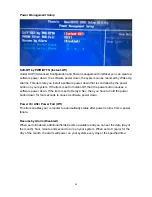
Page 44: ...e power button causes a software power down If the item is set to Delay 4 Sec then you have to hold the power button down for four seconds to cause a software power down Power On After Power Fail Off This item enables your computer to automatically status after power returns from a power failure Resume by Alarm Disabled When set to Enabled additional fields become available and you can set the dat...

Page 45: ...pecific option select and display that option and then press F7 Set Supervisor User Password When this function is selected the following message appears at the center of the screen to assist you in creating a password ENTER PASSWORD Type the password up to eight characters and press Enter The password typed now will clear any previously entered password from CMOS memory You will be asked to confi...

Page 46: ...ve and Exit dialog box appears press Y to save and exit or press N to return to the main menu Exit Without Saving Highlight this item and press Enter to discard any changes that you have made in the Setup Utility and exit the Setup Utility When the Exit Without Saving dialog box appears press Y to discard changes and exit or press N to return to the main menu ...

Page 47: ...creen A soft cotton cloth When cleaning the LCD screen it is important to use a soft cotton cloth rather than an old rag Some materials such as paper towels could cause scratches and damage the LCD screen Solution of water and isopropyl alcohol This solution can be used along with the soft cotton cloth Computer wipes Only use these if they specifically state on the package they are designed for LC...

Reviews: