Bomag BW 177 D-4 Operating Instructions Manual Download Page 57

 Operation

BOMAG

57

BW 177 D-4

Cooling the interior

l

Close all windows completely.

l

Direct the air flow towards the body/face (a).

l

Switch on the fan (c).

l

If necessary switch off the heating (b).

l

Switch on the air conditioning system with ro-
tary switch (d) and regulate the temperature.

Reducing the humidity

l

In case of damp weather direct the air flow to-
wards the windscreen and door screens.

l

Switch on the fan with the rotary switch (c).

l

Regulate the temperature to "Max" with the ro-
tary switch (b).

l

Switch the air conditioning (d) on.

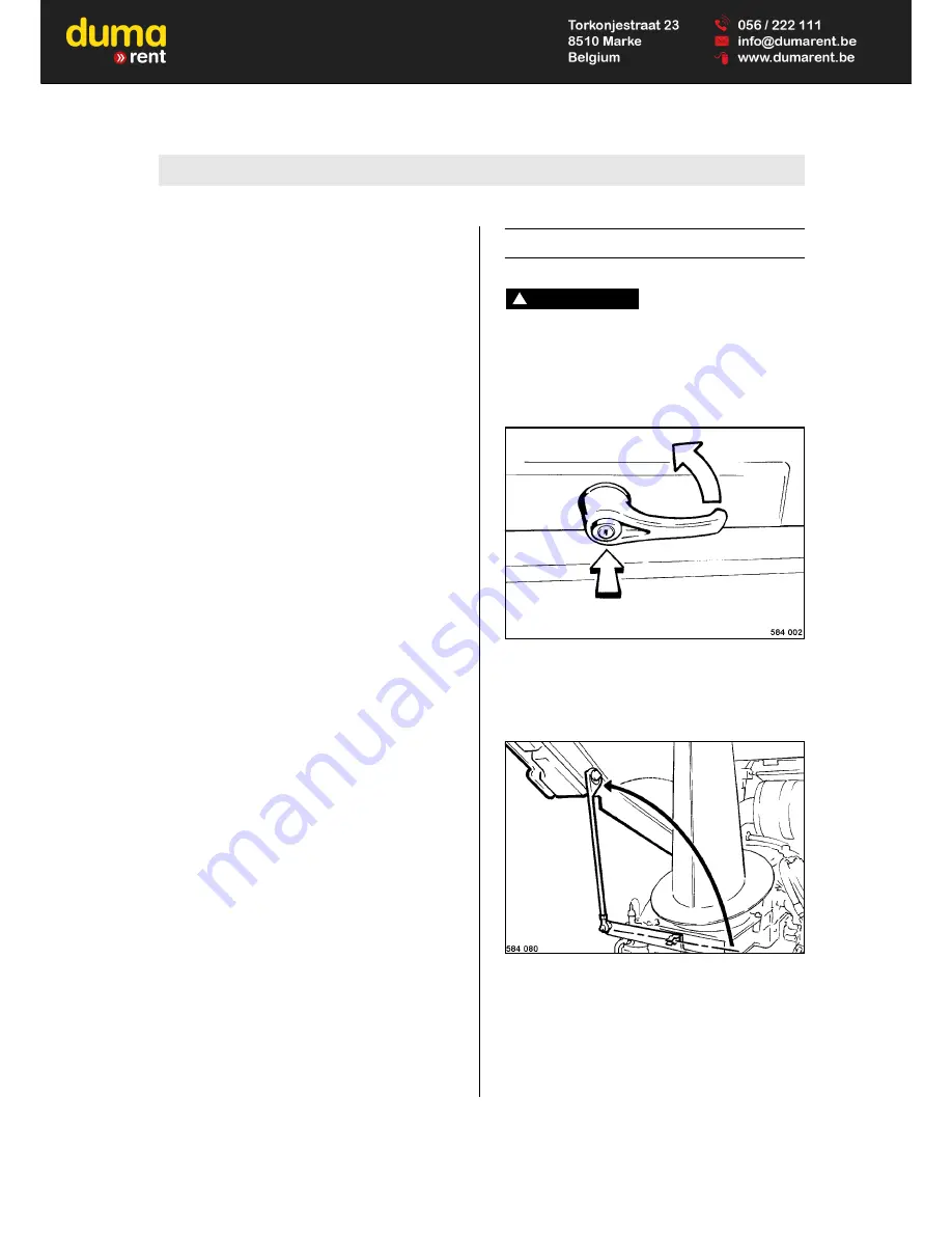
5.14 Operating the hood

Danger

!

Danger of accident!

If the hood needs to be opened further for 
maintenance or repair work, support it safely.

Bottom position

Fig. 75 

l

Unlock the lock (Fig. 75).

l

To open the hood press in the button and turn 
the handle.

Fig. 76 

l

Pull the support out of the bracket and support 
the hood (Fig. 76).

Top position

l

Push the hood to top position.

Summary of Contents for BW 177 D-4

Page 1: ...Operating instructions Maintenance instructions Original operating instructions 12 2012 Catalogue No 008 053 41 BW 177 D 4 S N 101 583 27 1241 Single drum roller...

Page 2: ......

Page 3: ...or operators and mainte nance personnel on construction sites Always keep this manual close at hand e g in the tool compartment of the machine or in a specially provided container These operating and...

Page 4: ...ngine number D Fig 4 Note i Supplement the above data together with the com missioning protocol During commissioning our organisation will in struct you in the operation and maintenance of the machine...

Page 5: ...the machine operating the parking brake 51 5 8 Shutting down the engine 52 5 9 Switching the vibration on and off 53 5 10 What to do in events of emergency 54 5 11 Adjusting the steering wheel 55 5 1...

Page 6: ...lacing the refrigerant compressor V belt 92 Every 500 operating hours 95 6 18 Changing engine oil and oil filter 95 6 19 Replace the fuel filter cartridge 96 6 20 Change the fuel pre filter cartridge...

Page 7: ...just the scrapers 125 6 42 Clean the machine 126 6 43 Change the tires 127 6 44 Change the fresh air filter in the cabin 127 6 45 Fill the provision tank for the windscreen washer system 128 6 46 Tigh...

Page 8: ...Table of Contents BOMAG 8 BW 177 D 4...

Page 9: ...BOMAG 9 BW 177 D 4 2 Technical Data...

Page 10: ...4190 Rear axle load CECE kg 3310 Static linear load kg cm 24 9 Travel characteristics Travel speed 1 km h 0 7 0 Travel speed 2 km h 0 11 0 Max gradability without with vibration 51 48 Drive Engine man...

Page 11: ...ring Type of steering Oscill articul Steering operation hydrostatic Inner track radius mm 3132 Steering angle 35 Oscillation angle 12 Vibration Drive system hydrostatic Frequency 1 2 Hz 30 40 Amplitud...

Page 12: ...ring operation these values may vary because of the existing operating conditions Noise value sound pressure level at the work place of the operator with cabin LpA 79 dB A determined acc to ISO 11204...

Page 13: ...BOMAG 13 BW 177 D 4 3 Safety regulations...

Page 14: ...or driver operator the manufacturer cannot be made liable Examples for unintended use are l work with vibration on hard concrete cured bi tumen layers or extremely frozen ground l driving on unstable...

Page 15: ...nes or parts of the machine Note i Paragraphs marked like this contain technical in formation for the optimal economical use of the machine Environment Paragraphs marked like this point out practic es...

Page 16: ...ll be working in Use your personal protective outfit hard hat safe ty boots etc Check before mounting the machine if l there are persons or obstructions beside or under the machine l the machine is fr...

Page 17: ...e cabin doors closed Do not adjust the driver s seat while driving Do not climb onto or off the machine while the ma chine is driving Change the travel direction only at standstill Do not use the mach...

Page 18: ...do not smoke Monitor the entire refuelling process Do not spill any fuel Catch running out fuel do not let it seep into the ground Wipe off spilled fuel Keep dirt and water away from the fuel A leakin...

Page 19: ...orking on the engine Do not work on the fuel system while the engine is running danger to life due to high pressures l Wait another minute after the engine has stopped l Keep out of the danger zone du...

Page 20: ...be repeatedly inspect ed by a specialist In connection with this inspection the drier collec tor unit must be visually examined twice every year During these inspections special attention must be pai...

Page 21: ...21 BW 177 D 4 Information and safety stickers decals on the machine Keep stickers decals complete see spare parts catalogue and fully legible and observe their meaning Replace damaged or illegible sti...

Page 22: ...od handle 4 Information sticker Vehicle voltage 12 V 5 Information sticker Lifting point 6 Information sticker Lashing points 7 Information sticker Engine oil drain port 8 Prohibition sticker High pre...

Page 23: ...177 D 4 Fig 8 Instruction sticker Always wear your seat belt Fig 9 Information sticker Emergency exit Fig 10 Information sticker Bio Hydraulic Oil 1 Fig 11 Information sticker Panolin 46 2 1 Optional...

Page 24: ...Safety regulations BOMAG 24 BW 177 D 4...

Page 25: ...BOMAG 25 BW 177 D 4 4 Indicators and Controls...

Page 26: ...Indicators and Controls BOMAG 26 BW 177 D 4 Fig 12...

Page 27: ...8 Travel lever 9 Rotary switch for vibration amplitude selection 10 Rotary switch for travel ranges 11 Emergency stop push button 12 Push button for warning horn 13 Rotary momentary contact switch fo...

Page 28: ...key can be pulled out Position I II Ignition on all control and warning lights in the instru ment cluster light up for 3 sec onds test function The oil pressure warning light flashes charge control l...

Page 29: ...d red Engine oil pressure warning light Flashes when the engine oil pressure is too low the warning buzzer sounds the engine is shut down after 10 seconds Check engine oil level repair the en gine if...

Page 30: ...off Position min and max Air conditioning control seg ment No 5 Vent for heating and ventilation driv er No 6 Vent for heating and ventilation foot well Fig 17 No 7 Push button vibration Switching the...

Page 31: ...he engine will be shut down and the brake will close Danger Danger of accident Operate only in emergency situations during operation do not use as a service brake The machine should only be started ag...

Page 32: ...ate with max engine speed Control the travel speed with the travel lever Fig 24 No 14 Rotary switch for direction indica tors1 Position mid dle Direction indicators disabled Position left or right Fro...

Page 33: ...left Light off Position right Working lights on with ignition switch in position I Fig 28 No 18 Lever steering wheel adjustment3 Danger Danger of accident Do not adjust the steering wheel while drivi...

Page 34: ...ent only with the ignition switch in position I or when the engine is running Fig 32 No 22 Fuses in electric junction box Danger Fire hazard Do not use fuses with higher ampere ratings and do not brid...

Page 35: ...reen wiper moves to end position and stops down Switches on front windscreen wiping Push button Front windscreen is sprayed during wiping c toggle switch for rear windscreen wiper washer up windscreen...

Page 36: ...for cabin light l cabin light Fig 37 No 25 Main fuse for battery 125A F00 No 26 Glow plug fuses 50A F158 50A F159 Fig 38 No 27 Speedometer1 Shows the travel speed of the machine outer scale km h inner...

Page 37: ...quency in Hz Fig 41 No 30 Voltmeter2 Shows the current on board voltage in Volt Fig 42 No 31 EVIBdisplay3 Is a compaction measuring unit for continuous dis play of the load bearing characteristics MN...

Page 38: ...sh button F7 PRINT only BTM prof 6 Push button F8 DELETE 7 Vibration frequency display 8 Rotary switch setting of nominal value 9 Push button F14 nominal value increase 10 Push button F13 nominal valu...

Page 39: ...con trol field F5 CONTINUE or the red control field F6 FINISHED will light up No 5 Button F 7 Print1 To print out the measuring data saved during the last pass press button F7 PRINT short actuation L...

Page 40: ...P1 is not used No 15 Button F10 is not used No 16 Button F9 is not used No 17 Speed display Shows the travel speed of the machine No 18 Amplitude display This gauge shows the current vertical amplitu...

Page 41: ...Indicators and Controls BOMAG 41 BW 177 D 4 4 5 Line diagram1 EVIB Fig 44 1 only BTM prof...

Page 42: ...ter division in longitudinal direction 16 Marking thick line excessive jumping tum bling of the drum 17 Longitudinal raster line 18 Measuring value raster line 19 Diagram line 20 Marking thin line jum...

Page 43: ...e same travel speed in order to avoid a falsification of the measuring results No 14 Track length Measured track length between START and STOP No 15 Raster division in longitudinal direc tion Is used...

Page 44: ...Indicators and Controls BOMAG 44 BW 177 D 4...

Page 45: ...BOMAG 45 BW 177 D 4 5 Operation...

Page 46: ...erve strictly the safety regulations in the corresponding section of this instruc tion manual l Park the machine on ground as level as possi ble Check l fuel tank and fuel lines for leaks l screw join...

Page 47: ...up with every digit l Press the diamond button l The electronic immobilizer is now disarmed and the engine can be started within the next 15 minutes 5 4 Starting the engine Danger Danger of accident...

Page 48: ...t d flashes the charge control light f and the parking brake warning light k stay on Under cold ambient temperatures the preheating control lamp b will also light up Do not start be fore the preheatin...

Page 49: ...tric system l Bridge the machine only with a 12 Volt auxilia ry battery l When jump starting with an external battery connect both plus poles first l Then connect the ground cable first to the mi nus...

Page 50: ...e driv ing with the machine With the door opened and the machine fully articulated extreme os cillations of the machine may damage the door Note i The machine is equipped with a seat contact switch sa...

Page 51: ...r a moment in 0 position until the machine has stopped before actuating to the new travel direction Do not operate jerkily Control the travel speed with the travel lever When driving up and down incli...

Page 52: ...g 61 lights up Note i The parking brake also closes automatically when shutting the engine down Fig 62 l Turn the momentary contact switch for engine speed Fig 62 anti clockwise to position MIN idle s...

Page 53: ...ger of bearing damage Do not activate the vibration on hard frozen concrete ground Fig 64 l Turn the rotary switch for travel speed range selection Fig 64 to position turtle Pre selecting the vibratio...

Page 54: ...of danger actuate the emergency stop switch immediate ly Start travel operation of the machine only after the danger that caused the actuation of the emergency stop switch has been eliminated Caution...

Page 55: ...steering wheel1 Fig 71 l Adjustment of steering wheel in height pull le ver Fig 71 up and move the steering wheel to the desired height l Adjustment of steering wheel inclination press lever down and...

Page 56: ...lowest position 5 13 Operating the heating air conditioning system1 Caution Always keep the air inlet slots on the cabin free of snow foliage etc Note i The heating power depends on the coolant tem p...

Page 57: ...ow to wards the windscreen and door screens l Switch on the fan with the rotary switch c l Regulate the temperature to Max with the ro tary switch b l Switch the air conditioning d on 5 14 Operating t...

Page 58: ...Secure the hood i n the protection tube with spring plug 5 15 BVC BTM05 settings before start up Switching between metric and imperial units Fig 78 l Turn the starter switch to position I Fig 78 The...

Page 59: ...Imperial 1 imperial units Fig 82 l Press F14 Fig 82 to save the selection The symbol Save lights green for a moment to confirm Note i After releasing the key F14 the system automat ically returns to...

Page 60: ...itch to position I Fig 84 The control unit shows the start screen Fig 85 l Press Fig 85 to change to the menu screen Fig 86 l Press F6 Fig 86 to change to the Printer language selection screen Fig 87...

Page 61: ...only be compared if the re cording of measuring values took place in operat ing mode Manual with the same amplitude frequency and travel speed and on exactly the same track Measuring values must only...

Page 62: ...93 Caution Since the transducer unit is mounted on the left hand side of the drum it is necessary to ar range the tracks so that track 1 is processed first followed by further tracks offset to the lef...

Page 63: ...s up to the pre adjusted travel speed Caution Differences in the travel speeds falsify the measuring result Fig 97 l Switch the vibration on Fig 97 Caution Before reaching mark 1 the nominal exciter s...

Page 64: ...green control field to the left of F5 Fig 100 goes out and the red control field F6 be low lights up after pressing the stop button F6 The compaction process on this track is finished Criterion for a...

Page 65: ...the paper provision before starting work Change the paper roll if a red stripe appears on the paper Fig 102 l At the end of the measurement press push button F7 PRINT Fig 102 short actuation Line diag...

Page 66: ...F6 FINISHED goes out and the green control field F5 CONTINUE lights up BTM plus prof is ready to compact the next track 5 19 Changing the paper roll in the measuring value print er1 Note i Use a new p...

Page 67: ...suring value printer1 Note i In case of faint or poorly legible diagrams the print er ribbon needs to be replaced Fig 107 l Unscrew the star handles Fig 107 and re move the cover Fig 108 l Lift the to...

Page 68: ...owing speed 1 km h max towing distance 500 m l Secure the machine with wheel chocks against unintentional rolling Fig 109 l Attach chains Fig 109 or towing ropes to the lifting points l Open the engin...

Page 69: ...ef valves completely out again and tighten the counter nuts l Turn all brake releasing screws of the axle evenly back out until they are light moving again Fig 113 l Turn the brake releasing screws Fi...

Page 70: ...ng or lashing down the machine Do not use a damaged or in any other way im paired lifting and lashing eyes Lift the machine only with suitable lifting gear Use only safe lifting gear of sufficient loa...

Page 71: ...Fig 118 l For lifting use the four lifting eyes Fig 118 and appropriate lifting gear Fig 119 Position of centre of gravity Fig 119 Note i The tolerances account for all possible options such as cabin...

Page 72: ...Operation BOMAG 72 BW 177 D 4...

Page 73: ...BOMAG 73 BW 177 D 4 6 Maintenance...

Page 74: ...ess of the fuel l Keep fuel free of contaminants and water since this will damage the injection elements of the engine l Drums with inside zinc lining are not suitable to store fuel l When choosing th...

Page 75: ...ank opening unnecessarily open but cover it so that nothing can fall in 6 2 Fuels and lubricants Engine oil Quality For use in DEUTZ engines the lubrication oils are classified in DEUTZ Lubrication Oi...

Page 76: ...hur content of less than 0 5 and ensure strict cleanliness when filling in A higher sulphur content has a negative effect on the oil change intervals The fuel level should always be topped up in due t...

Page 77: ...oil manufacturer for details Caution Check the filter more frequently after this change Perform regular oil analyses for content of wa ter and mineral oil Replace the hydraulic oil filter element ever...

Page 78: ...15W 40 15 C to 40 C SAE 5W 40 30 C to 40 C Fuel Diesel Winter diesel fuel approx 150 litres Hydraulic system Hydraulic oil ISO HLP 46 BOMAG 009 930 09 20 l or ester based biodegradable hydraulic oil a...

Page 79: ...rmal level after approx 100 to 250 operating hours After a running in time of 30 minutes l Retighten the V belt After 250 operating hours l Retighten bolted connections on intake and exhaust tubes oil...

Page 80: ...pressure X 6 11 Clean radiator cooling fins X 6 12 Clean the cooling fins on the hydrau lic oil cooler X 6 13 Check the oil level in the drive axle X 6 14 Check the oil level in the wheel hubs X 6 15...

Page 81: ...32 Retighten the fastening of the axle on the frame X 6 33 Tighten the wheel nuts5 see foot note X 6 34 Check the ROPS X 6 35 Check the travel control X 6 36 Change hydraulic oil and breather filter1...

Page 82: ...instructions check the valve clearance after 250 and 1000 operating hours then every 1000 operating hours 3 Running in instructions oil change after 250 500 and 1000 operating hours then every 1000 op...

Page 83: ...ust always be between the MIN and MAX marks If the oil level is too low top up oil to the MAX mark immediately 6 7 Checking the fuel level Caution Do not drive the fuel tank dry as otherwise the fuel...

Page 84: ...filled with Panolin HLP Synth 46 use always the same oil to top up With other ester based oils consult the lubrica tion oil service of the respective oil manufac turer If during the daily inspection...

Page 85: ...not be determined precisely After taking the engine into operation you should therefore check the filter bowl initially every day for signs of water Environment Catch running out fuel and dispose of...

Page 86: ...Every 10 operating hours BOMAG 86 BW 177 D 4...

Page 87: ...f injury Perform cleaning work only after the engine has cooled down and with the engine stopped Note i Dirt on fan blades and oil cooler reduce the cooling effect Dirt deposits in these areas are sub...

Page 88: ...o avoid corrosion 6 12 Cleaning the cooling fins on the hydraulic oil cooler Danger Danger of injury Perform cleaning work only after the engine has cooled down and with the engine stopped Caution Do...

Page 89: ...hile and spray it off with a strong water jet l Run the engine warm for a while to avoid cor rosion 6 13 Check the oil level in the drive axle l Park the machine on level ground Fig 130 l Unscrew the...

Page 90: ...e oil level must reach the bottom edge of the bore top up oil if neces sary l Screw the plug back in tightly 6 15 Check the oil level in the vi bration bearings Fig 132 l Move the drum until the level...

Page 91: ...itch for engine speed Fig 134 clockwise to MAX Fig 135 l Shift the travel lever Fig 135 out of braking position to the left to disengage l Pull the travel lever back first l Then shift the travel leve...

Page 92: ...damage and cracks Re place damaged or cracked V belts l Check with thumb pressure whether the V belt can be depressed more than 10 to 15 mm 0 4 0 6 inches between the V belt pulleys retighten if nece...

Page 93: ...d 3 Fig 139 l Press the compressor against the direction of arrow completely against the engine l Take the old V belt off l Fit the new V belt to the V belt pulleys l Tension the V belt as previously...

Page 94: ...Every 250 operating hours BOMAG 94 BW 177 D 4...

Page 95: ...nd dispose of environ mentally together with the oil filter cartridge Fig 140 l Unscrew the drain plug Fig 140 and catch running out oil l Turn the drain plug tightly back in Fig 141 l Unscrew the fil...

Page 96: ...anger Health hazard Do not inhale any fuel fumes Caution Ensure strict cleanliness Thoroughly clean the area around the fuel filters After work on the fuel system bleed the sys tem perform a test run...

Page 97: ...20 Change the fuel pre filter cartridge Danger Fire hazard When working on the fuel system do not use open fire do not smoke and do not spill any fu el Danger Health hazard Do not inhale any fuel fum...

Page 98: ...e water separator l Screw the water separator on by hand until the seal contacts l Tighten the water separator for another half turn Caution The filter cartridge must not be pre filled Dan ger of cont...

Page 99: ...ttery at regular intervals At least once per month Reference values 12 6 V fully charged 12 3 V 50 discharged l Recharge the battery immediately after an open circuit voltage of 12 25 V or less is rea...

Page 100: ...nd drain off ap prox 5 litres of fuel l Turn the cap tightly back in 6 23 Checking the V belt tension tightening Check the V belt Fig 152 l Inspect the entire circumference of the V belt visually for...

Page 101: ...the machine Caution A soiled condenser results in a considerable reduction of air conditioning power Under extremely dusty conditions it may be necessary to clean the condenser several times per day...

Page 102: ...ler Note i The adjusted temperature must be below the actu al temperature inside the cabin so that the com pressor will be switched on Fig 157 l Check whether the white float Fig 157 inside the inspec...

Page 103: ...ervoirs must be repeated ly inspected by a specialist In this sense repeated inspections are external examina tions normally on pressure reservoirs in oper ation In connection with this inspection the...

Page 104: ...bypass filter2 Danger Danger of scalding Danger of scalding by hot oil when unscrewing the oil filter Caution If the filter has to be changed together with the hydraulic oil the filter must only be c...

Page 105: ...Every 500 operating hours BOMAG 105 BW 177 D 4 Fig 163 l Unscrew the fastening screws Fig 163 and take off the cover l Replace the filter element attach the cover and fasten it with the screw...

Page 106: ...Every 500 operating hours BOMAG 106 BW 177 D 4...

Page 107: ...over Fig 164 Fig 165 l Disconnect the cable from the shut down sole noid Fig 165 Fig 166 l Crank the engine with the starter until both valves on cylinder 1 Fig 166 are overlap ping Note i Overlapping...

Page 108: ...a short test run check the engine for leaks 6 28 Check the engine mounts Fig 169 l Check the fastening of intake and exhaust tubes Fig 169 on the cylinder heads for tight fit l Check sockets and clam...

Page 109: ...oil and dispose of environ mentally Fig 171 l Move the drum until the drain and filler plug Fig 171 is in lowest position l Clean and unscrew drain and filler plug Fig 172 l Once all oil has been dra...

Page 110: ...lugs are of slightly different design Perform the oil change ac cordingly l Park the machine on level ground Fig 173 l Clean and unscrew all level inspection and drain plugs Fig 173 l Drain and catch...

Page 111: ...efer to the table of fuels and lubricants Environment Catch running out oil and dispose of environ mentally Fig 175 l Move the drive wheel until the plug Fig 175 is in bottom position l Clean and unsc...

Page 112: ...n the fastening of the axle on the frame Fig 177 l Check all fastening nuts on axle mounting bolts Fig 177 for tight fit 6 33 Tightening the wheel nuts Fig 178 l Tighten the wheel nuts Fig 178 in a cr...

Page 113: ...ation are signs for damage or loosened fastening elements l Check the fastening screws for the cabin ROPS to the operator s stand for tight fit l Check the rubber buffers of the operator s plat form s...

Page 114: ...Every 1000 operating hours BOMAG 114 BW 177 D 4...

Page 115: ...Use only lint free cleaning cloths For quality and quantity of oil refer to the table of fuels and lubricants When changing from mineral oil based hydrau lic oil to an ester based biologically degrada...

Page 116: ...raulic oil the filter should in any case be changed after the oil change and the test run Do not use the oil in the filter bowl Environment Catch running out oil dispose of oil and filter element envi...

Page 117: ...fective compo nents Nonobservance may lead to total damage of the hydraulic system Do not clean or reuse the filter element l Take the old filter element 3 out and clean the filter bowl and the thread...

Page 118: ...Every 2000 operating hours BOMAG 118 BW 177 D 4...

Page 119: ...Every 3000 operating hours BOMAG 119 BW 177 D 4 Every 3000 operating hours 6 38 Replace the injection valve Note i This work must only be performed by authorized service personnel...

Page 120: ...Every 3000 operating hours BOMAG 120 BW 177 D 4...

Page 121: ...y be changed by a specialist workshop or by the After Sales Serv ice of BOMAG Do not retension toothed belts replace them together with the idler pulley Replace a toothed belt at the latest after 5 ye...

Page 122: ...Every 5000 operating hours BOMAG 122 BW 177 D 4...

Page 123: ...er el ement If in doubt use a new air filter If the air filter is damaged the safety element must be replaced as well The safety element must not be cleaned Note i We generally recommend to renew the...

Page 124: ...inside to outside by moving the gun up and down inside the element until it if free of dust Fig 190 l Examine the air filter with a torch for cracks and holes in the paper bellows Fig 190 l In case o...

Page 125: ...ff l Pull the safety element Fig 192 out by turn ing it lightly l Push in a new safety filter element l Insert the air filter and reassemble the housing cover 6 41 Adjust the scrapers Smooth drum l Ch...

Page 126: ...using a steam cleaner for cleaning do not subject electrical parts and insulation ma terial to the direct jet or cover these items be forehand Allow the engine to cool down before cleaning Fig 195 l...

Page 127: ...p until the wheel is off the ground l Unscrew the wheel nuts and take the wheel off Fig 196 l Attach a new wheel Fig 196 and tighten the wheel nuts crosswise with 550 Nm 405 ft lb l Check the tire pre...

Page 128: ...6 46 Tightening torques Fig 199 Strength classes for screws with untreated non lubricated surface Screw quality designations are stamped on the screw heads 8 8 8G 10 9 10K 12 9 12K l Axle frame M 24x...

Page 129: ...th this conserving mixture and the new engine oil has been dis tributed to all parts l Now crank the engine several times without ignition to spray the combustion chambers l Take the V belts off and s...

Page 130: ...As required BOMAG 130 BW 177 D 4...

Page 131: ...BOMAG 131 BW 177 D 4 7 Trouble shooting...

Page 132: ...insufficient mainte nance Whenever a fault occurs you should there fore thoroughly read these instruction on correct operation and maintenance If you cannot locate the cause of a fault or rectify it y...

Page 133: ...ics Fig 202 Note i The screen with the currently available fault codes is displayed Fig 203 l Currently present faults are indicated by a cor responding fault code in the field Actual Er rors l Press...

Page 134: ...ease Especially during winter the use of too viscous engine oil Use engine oil suitable for the ambient temperature Fuel supply restricted in winter fuel sys tem clogged due to paraffin separation Cha...

Page 135: ...cessary Exhaust gas turbo charger defective Have examined by a specialist Charge air hose leaking Check fastening and connections Incorrect valve clearance Adjust the valve clearance Injection valve d...

Page 136: ...Trouble shooting BOMAG 136 BW 177 D 4...

Page 137: ...BOMAG 137 BW 177 D 4 8 Cab assembly before initial start up...

Page 138: ...hibited for safety reasons Original parts and accessories have been special ly designed for this machine We wish to make ex plicitly clear that we have not tested or approved any parts or accessories...

Page 139: ...straps must strictly be removed to ensure safe and reliable function of the seat contact switch Check the 4 lifting eyes on the cabin roof for tight fit Fasten the lifting gear to all four lifting ey...

Page 140: ...lifting gear chains or ropes of sufficient load bearing capacity The minimum load bear ing capacity of the crane must be 1000 kg Do not stand or step under loads being lifted l Clean the operator s s...

Page 141: ...r sticking on the sealing tape because the sealing tape will swell Fig 208 l Spray the sealing tape with soapsuds Fig 208 to be able to slide the cabin on the oper ator s stand Fig 209 l Slowly lower...

Page 142: ...match the cabin can be moved into position by means of a crow bar Fig 212 Fig 213 l Tighten the bottom fastening screw on the ac cess side Fig 213 with 578 Nm Fig 214 l Loosen both fastening screws Fi...

Page 143: ...the right hand side with 578 Nm Fig 216 Fig 217 l Tighten the rear inside fastening screw on the right hand side with 578 Nm Fig 217 Fig 218 l Turn nuts with washers onto both studs and tighten with...

Page 144: ...ig 221 Fig 222 l Insert the foot mat 1 Fig 222 Fig 223 l Attach the step plate 1 Fig 223 and tighten the three fastening screws 2 Fig 224 l Insert the dashboard and fasten it with four fastening screw...

Page 145: ...cope of the function test Observe identical hose diameters when connect ing Fig 227 l Plug on both connecting plugs for the washing water pumps Fig 227 Fig 228 l Plug on the hoses for the washing wate...

Page 146: ...dlights direction indicators and interior light to check their func tion l Operate the switches for front and rear wind screen washer system and check their correct function Note i If the function of...

Page 147: ...BOMAG 147 BW 177 D 4 9 Disposal...

Page 148: ...he battery contains acid Do not let acid come in contact with skin or clothes Wear protective clothing l Remove the batteries and dispose of in com pliance with legal regulations Environment Catch all...

Page 149: ......

Page 150: ......

Page 151: ...Vibration rollers MECALAC AX700 Our vibration rollers are used for minor compaction work such as the bottom layers rolling in of crushed stones construction of footpaths kerbs and drives etc Renting...

Reviews: