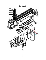
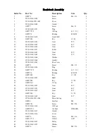
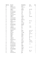
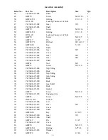
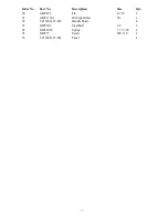
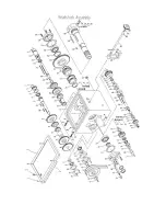
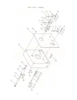
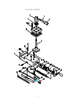
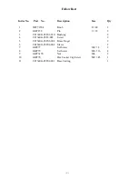
Bolton Tools BT1340G/1 Operation Manual Download Page 38


33


Gearbox Assembly 

Index No. 

Part No. 

Description 

Size 

Qty. 

GB/T70 

Screw 

M6

×

16 

CZ1340G-03-007 

Shaft Cover 


CZ1340G-07-008 

Gear(30T,54T,56T,57T, 

60T,63T,66T,69T,7
8T) 

CZ1340G-07-013 

Shaft 


GB/T1096 

Key 

5

×

18 

GB/T1096 

Key 

5

×

45 

GB/T894 

C-Clip 

20 

10 

GB/T276 

Bearing 

6004 

11 

CZ1340G-07-018 

Gasket 


12 

CZ1340G-07-021 

Cover 


13 

GB/T70 

Screw 

M5

×

12 

18 

14 

CZ1340G-07-022 

Shaft 


15 

GB/T117 

Pin 

3

×

32 

16 

GB/T70 

Screw 

M6

×

20 

17 

CZ1340G-07-009 

Cover 


18 

GB/T1155 

Oil Ball 

19 

CZ1340G-07-010 

Gasket 


20 

GB/T276 

Bearing 

6203 

21 

CZ1340G-07-012 

Cover 


22 

GB/T894 

C-Clip 

16 

23 

CZ1340G-07-011 

Gear 

24T,16T 

24 

GB/T276 

Bearing 

6202 

25 

CZ1340G-07-001 

Casting 


26 

GB/T879 

Pin 

5

×

20 

27 

GB/T70 

Screw 

M8

×

65                         

28 

CZ1340G-07-049 

Collar 


29 

CM1224C-03-034 

Oil Cover 


30 

GB/T894 

C-Clip 

26 

31 

CZ1340G-07-053 

Gear 

24T 

32 

CZ1340G-07-052 

Gear 

28T 

33 

CZ1340G-07-051 

Gear 


34 

GB/T1096 

Key 

4

×

22 

35 

CZ1340G-07-005 

Cover 


36 

CZ1340G-07-004 

Gasket 


37 

CZ1340G-07-015 

Shaft 


38 

GB/T1096 

Key 

4

×

55 

39 

CZ1340G-07-006 

Gear 

24T 

40 

CZ1340G-07-007 

Gear 

16T 

41 

CZ1340G-07-014 

Gear 

32T 

42 

GB/T77 

Screw 

M5

×

16 

43 

CZ1340G-07-059 

Cover 


44 

CZ1340G-07-047 

Gear 

32T 

45 

CZ1340G-07-045 

Gasket 


46 

CZ1340G-07-044 

Cover 


47 

CZ1340G-07-002 

Gear 

16T 

Summary of Contents for BT1340G/1

Page 1: ...BT1340G 1 BENCH LATHE OPERATION MANUAL...

Page 2: ...REVENTING BODY CONTACT WITH GROUNDED SURFACES For example Pipes radiators ranges refrigerator enclosures KEEP GUARDS IN PLACE AND IN WORKING ORDER REMOVE ADJUSTING KEYS AND WRENCHES Form habit of chec...

Page 3: ...DISCONNECT TOOLS FROM POWER SOURCE Before servicing and when changing accessories such as blades bits cutters or when mounting and re mounting motor 1 2 15 AVOID ACCIDENTAL STARTING Make sure switch i...

Page 4: ...ting and retain for future use 2 1 Wear eye protection 2 2 Never attempt any operation or adjustment if proceedure is not understood 2 3 Keep fingers away from revolving parts and cutting tools while...

Page 5: ...d disc workpieces of middle or small types They can also be used to cut imperial diameter and module threads And with compact construction and reasonable composition they can cut very well They are ea...

Page 6: ...5 Number Of Spindle Speeds 8 Range Of Spindle Speeds 70 2000 r p m Carriage toolpost Cross slide Width 4 5 8 118mm Travel 6 5 16 160mm Toolpost Width 3 76mm Travel 2 11 16 68mm Leadscrew Diameter 7 8...

Page 7: ...nge gears 4 2 Setting up the machine Locate the machine on a solid foundation A concrete floor is the best for the machine allowing sufficient area for easy work and maintenance The machine may be use...

Page 8: ...Electrical wiring diagram 3 phases Single phase...

Page 9: ...itted at the bottom left hand end of the head stock accessible after removal of the end cover and the change gears with swing frame Open the headstock cover to fill the oil check oil level weekly and...

Page 10: ...t shaft bracket of gearboxs handwheel bracket of apron feed rod bracket of carriage saddle cross slide toolpost thread dial indicator tailstock and the bracket which holds the leadscrew feed rod handi...

Page 11: ...eadscrew Feed rod 2 32 Once a day 9 Tailstock 3 32 Once a day 10 Support seat 2 32 Once a day Operation symbols for operation Electrical Danger Diametral pitch thread Coolant Module pitch thread Imper...

Page 12: ...l traverse hand wheel 9 cross traverse hand wheel 10 Follow rest 11 Toolpost handle 12 Toolpost traverse handle 13 Tailstock quill clamping lever 14 Tailstock quill traverse hand wheel 15 Tailstock se...

Page 13: ...forward reverse switch No 1 C Speeds of spindle change The speeds of spindle are changed by means of HIGH LOW speed selector No 5 and four steps speed selector No 4 The spindle s speed chart shows 4...

Page 14: ...ith its index line between the two vee marks on the nose Fig 2 DO NOT INTER CHANGE CHUCKS OR OTHEY SPINDLE MOUNTING ITDMS BETWEEN LATHES WITHOUT GHECKING EACH CAM FOR CORRECT LOCKING TO ADJUST CAM LOC...

Page 15: ...gitudinal feed can be obtained On the contrary if the selector No 20 is pushed in and operated downward across feed will be obtained Feed direction can be changed by feed direction selector No 3 at th...

Page 16: ...b Longitudinal and cross feed table in metric lead screw 2 Thread table a Thread table for imperial lead screw...

Page 17: ...b Thread table for metric lead screw...

Page 18: ...sed for thread cutting to engage with lead screw To cut threads on the chart close the lead screw nut at the appointed line of the dial according to the indicator chart Ensure the appropriate dial lin...

Page 19: ...the whole drive by means of the spindle forward reverse switch No 3 at each end of the thread cutting pass while at the same time relieving or increasing the cut as required 7 LATHE ALIGNMENT When the...

Page 20: ...ide A Wear on the taper gib strip B may be adjusted B for by clockwise rotation of the slotted head screw A on the front of the cross slide The procedure is to first slacken the similar screw at the r...

Page 21: ...screw is fitted in the rear face of the body Set over adjustment is made as follows Unclamp the tailstock by operating the clamp lever downward Slacken the rear location screw Then alternatively slack...

Page 22: ...on and off button and examine the sensitiveness of starting stopping and pilot lamp strictly 2 The sensitivity and reliability of mechanical control device control levers for forward and reverse main...

Page 23: ...g and collection of all tools All tools should be kept clean first then put back to original position 2 Proper position of tailstock carriage tool holder Tailstock carriage tool holder should be place...

Page 24: ...and nut whether they are right or not 4 The stability of machine body Tighten up the foundation bolts of machine body to the ground and make the body stable 8 4 5YEARLY INSPECTION 1 Positioning and l...

Page 25: ...ring Replace bearing 7 Bearing in its not improper position Dismantle and reassemble it 8 Bent or sprung main spindle Replace main spindle 9 Too much end thrust Adjust thrust nut Oil leakage from gear...

Page 26: ...long for extension Replace with rigid tools or reset the tools 26 Tool fixed to holder not tight enough Tighten tool again 27 Unbalances of workpiece or chuck when high speed revolution Balance or re...

Page 27: ...ead screw holder 35 Excessive clearance between saddle or cross slide or cross slide and tool post slide Adjust slide gib to proper position 36 Worn thread or nut in cross slide or tool post slide Adj...

Page 28: ......

Page 29: ...GB T1155 Oil Ball 8 2 19 GB T70 Hex Socket Cap Screw M6 16 2 20 GB T119 Pin 8 25 1 21 CZ1340G 01 025 Handle 1 22 CZ1340G 01 030 Collar 1 23 CZ1340G 01 028 Key 1 24 CZ1340G 01 029 Brake Ring 1 25 GB T...

Page 30: ...Index No Part No Description Size Qty 45 CZ1340G 01 005 Motor Mounting Plate 1 46 CZ1340G 02 001 Lock Nut 2 47 CZ1340G 00 005 Cover 1 48 CZ1340G 02 002 Screw 1 49 CZ1340G 02 002 Screw 1...

Page 31: ......

Page 32: ...G 02 064 Gasket 1 19 CZ1340G 02 063 Rear Cover 1 20 GB T70 Screw M4 12 3 21 CZ1340G 02 026 Plug 1 22 GB T7757 2 Bearing 34 7 3 1 1 23 GB T276 Bearing 6203 P6 1 24 GB T1096 Key 6 120 1 25 CZ1340G 02 02...

Page 33: ...Lock Nut 1 63 CZ1340G 02 003 Spindle 1 64 GB T1096 Key 8 90 1 65 GB T1096 Key 6 40 1 66 CZ1340G 02 034 Cam 3 67 CZ1340G 02 035 Pin 3 68 GB T2089 Spring 0 6 3 10 3 69 GB T70 Screw M8 20 3 70 JB T7941 1...

Page 34: ...1 93 CZ1340G 02 056 Washer 1 94 GB T10708 3 Oil Seal 24 32 5 1 95 CZ1340G 02 057 Gear 40T 1 96 GB T97 1 Washer 12 1 97 GB T41 Nut M12 1 98 CZ1340G 02 024 Shift Lever 1 99 GB T7757 2 O Ring 11 8 1 8 2...

Page 35: ......

Page 36: ...0 Handle 1 17 GB T70 Screw M6 20 2 18 CZ1340G 02 042 Hub 1 19 GB T894 1 C Clip 30 1 20 GB T818 Screw M4 6 6 21 CZ1340G 02T01 006 Name Plate 1 22 CZ1340G 02T01 005 Inlaid Block 1 23 GB T7757 2 O Ring 2...

Page 37: ......

Page 38: ...ring 6203 1 21 CZ1340G 07 012 Cover 1 22 GB T894 C Clip 16 2 23 CZ1340G 07 011 Gear 24T 16T 1 24 GB T276 Bearing 6202 9 25 CZ1340G 07 001 Casting 1 26 GB T879 Pin 5 20 2 27 GB T70 Screw M8 65 2 28 CZ1...

Page 39: ...1 61 CZ1340G 07 027 Shaft 2 62 GB T41 Nut M5 4 63 GB T75 Screw M5 16 4 64 CZ1340G 07 024 Slip Fitting 1 65 CZ1340G 07 026 Rack 1 66 CZ1340G 07 023 Slip Fitting 1 67 CZ1340G 07 029 Slip Fitting 2 68 C...

Page 40: ...Description Size Qty 90 GB T879 Pin 4 25 2 91 GB T1160 1 Oil Sight Glass 20 1 92 CZ1340G 07 036 Handle Body 4 93 GB T308 Steel Ball 6 5 4 94 GB T2089 Spring 1 5 20 4 95 GB T77 Screw M8 10 4 96 CZ1340...

Page 41: ......

Page 42: ...GB T1096 Key A5 18 1 20 JB T7940 4 Oil Ball 8 1 21 CZ1340G 04 003 Dial seat 1 22 GB T70 Screw M6 25 3 23 GB T78 Screw M5 6 1 24 CZ1340G 04 048 Dial 1 25 CZ1340G 04 045 Hand wheel 1 26 CZ1340G 04 046 W...

Page 43: ...M6 35 2 64 GB T6170 Nut M6 2 65 GB T5781 Screw M5 16 3 66 CZ1340G 04 019 Nut seat 1 67 GB T6170 Nut M5 3 68 GB T77 Screw M5 16 3 69 CZ1340G 04 021 Gib 1 70 GB T119 Pin 6 12 2 71 CZ1340G 04 017 Shaft...

Page 44: ......

Page 45: ...70 Nut M6 4 22 GB T71 Screw M6 16 4 23 GB T5781 Screw M8 25 3 24 JB T7940 4 Oil Ball 8 2 25 CZ1340G 05 019 Sleeve 1 26 GB T1096 Key 4 4 20 1 27 CZ1340G 05 018 Gear Shaft 1 28 GB T68 Screw M3 6 1 29 GB...

Page 46: ......

Page 47: ...4 4 18 1 11 CZ1340G 05 028 Top Slide 1 12 JB T7940 4 Oil Ball 6 3 13 GB T78 85 Screw M6 10 1 14 GB T301 Bearing 51101 2 15 CZ1340G 05 034 Collar 1 16 GB T70 Screw M6 20 2 17 GB T6173 Nut M12 1 2 18 GB...

Page 48: ......

Page 49: ...Z1340G 06 004 Nut 1 16 GB T70 85 Screw M4 12 3 17 CZ1340G 06 006 Index ring 1 18 CZ1340G 06 003 Screw 1 19 GB T1096 Key 4 16 1 20 CZ1340G 06 010 Handle 4 21 GB T301 Bearing 51102 1 22 CZ1340G 06 005 F...

Page 50: ......

Page 51: ...1 8 GB T818 Screw M4 8 10 9 LC1 D259 Contactor 2 10 GB T818 Screw M4 12 6 11 CZ1340G 09 006 Label 7 12 GB T41 Nut M6 4 13 GB T818 Screw M4 16 2 14 JH9 1 5ZG Terminal plate 1 15 CZ1340G 09 009 Earth te...

Page 52: ......

Page 53: ...79 Pin 3 18 2 3 CZ1340G 05T03 010 Bushing 2 4 CZ1340G 05T2 003 Screw 2 5 CZ1340G 05T03 008 Brass Finger 2 6 CZ1340G 05T02 002 Sleeve 2 7 GB T77 Set Screw M6 8 2 8 GB T79 Set Screw M6 16 2 9 GB T6170 N...

Page 54: ......

Page 55: ...CZ1340G 05T03 007 Bolt M6 30 1 8 GB T79 Set Screw M6 16 3 9 CZ1340G 05T03 003 Base Casting 1 10 CZ1340G 05T03 002 Clamp Screw 1 11 CZ1340G 05T03 001 Clamp Pad 1 12 GB T96 Flat Washer 12 1 13 GB T6170...

Reviews: