


13
6.2 SPINDLE NOSE (CAM LOCK D1-4”)
MOUNTING OF CHUCKS, FACEPLATES AND OTHER SPINDLE MOUNTED
ATTACHMENTS
Ensure that the location faces on both nose and attachment are scrupulously cleaned.
Check that all the cams are in the release position (fig . 1)
Mount the attachment on to the spindle nose and lock each cam by turning it
clockwise using the key provided.
A reference line R1 (fig .1) should be scribed on each chuck or faceplate to coincide
with the reference line R on the spindle nose. assists subsequent re-mounting .
NOTE : For correct locking conditions each cam must tighten with its index line
between the two vee marks on the nose (Fig .2)
DO NOT INTER CHANGE CHUCKS OR OTHEY SPINDLE MOUNTING ITDMS
BETWEEN LATHES WITHOUT GHECKING EACH CAM FOR
CORRECT LOCKING TO ADJUST CAM LOCK STUDS
Remove Lockscrew (B)
Turn Stud (A) one full turn in or out as required
Refit and tighten leadscrew (B) (fig . 3)
Note : A datum ring (C ) is marked on each stud as a guide to the original or initial
setting .
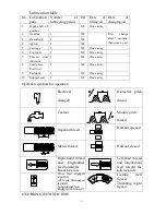
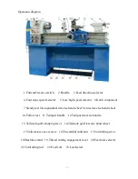
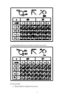
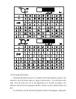
6.3 FEED AND THREAD SELECTION (refer to operation diagram)
All feeds and threads are given on the feed and thread tables, fitted on the front
of the end cover, by setting the feed selector handle.
(A)
Hand feed operation
The movement of carriage is made by the longitudinal feed hand wheel(No.8),
cross slide by the cross feed hand wheel(No.9) and tool post by the tool post feed
Summary of Contents for BT1340G/1
Page 1: ...BT1340G 1 BENCH LATHE OPERATION MANUAL...
Page 8: ...Electrical wiring diagram 3 phases Single phase...
Page 17: ...b Thread table for metric lead screw...
Page 28: ......
Page 31: ......
Page 35: ......
Page 37: ......
Page 41: ......
Page 44: ......
Page 46: ......
Page 48: ......
Page 50: ......
Page 52: ......
Page 54: ......