Program the Device Address
If the detector address is unknown or two devices have the same address then use the
Program Device Address command specifying a required address as the parameter.
Then remove the detector cover and ensure the LED is flashing indicating the
programming mode (frequent short flashes every 2 s). Next, press the tamper switch in
LLLS pattern, where L stands for long pressings (between 0.5 s and 2 s) while S
stands for short pressings (shorter than 0.5 s), pauses between pressings not
exceeding 3 s each.
If the address has changed successfully, the LED will be lit steady and a message
about detecting the device with the newly assigned address shall be displayed by a
network controller (S2000(M) or UProg Configuration Tool). Mark down the assigned
address on the marking field of the detector. If you’ve failed to assign the address, wait
for 3 s and repeat programming.
ENABLING/DISABLING LED INDICATION
On detector’s switching on the LED indication is enabled. To disable indication, press the tamper switch in LLSL pattern;
otherwise, to enable indication, press the tamper switch in LLSS pattern, where L stands for a long pressing (longer than
0.5 s) while S stands for a short pressing (shorter than 0.5 s). Pauses between pressings must not exceed 1 s each.
WALK TEST
The detector having been connected to the polling loop, its LED lights up indicating its start self-testing procedure. After
self-testing being completed successfully the LED switches off. To check the correctness of detector’s mounting, walk
through the detection zone several times. The detector is to be armed by the relevant command issued from the network
controller (the S2000 console). When an intrusion into the protected area is detected, the detector sends an alarm to the
network controller and its LED flashes triply. After issuing the alarm the detector will be ready to operate in two seconds. If
the detector’s case has been open, the detector sends the network controller a tamper alarm. The Tamper Restored
message will be issued to the network controller in 15 seconds since closing the case.
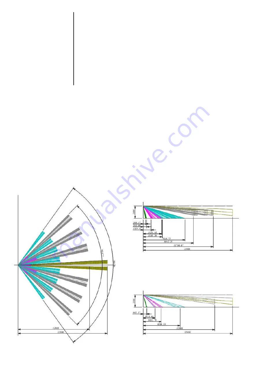
DETECTION PATTERN
Figure 2: S2000-IK Rev.03 Detection Pattern


