background image

11

CHAPTER 12:  LEAD WIRE MAINTENANCE

CHAPTER 11 :  

ATTACHMENT OF  ELECTRODE LEAD WIRES

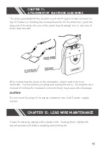
The wires provided with the system insert into the jack sockets located on 
top of the device.  Holding the insulated portion of the connector, push the 
plug end of the wire into one of the jacks (see drawing); one or two sets of 
wires may be used.

After connecting the wires to the stimulator, attach each wire to an 
electrode.  Use care when you plug and unplug the wires.  Jerking the wire 
instead of holding the insulated connector body may cause wire breakage.

CAUTION

Do not insert the plug of the patient lead wire into the AC power supply 
socket.

Clean the wires by wiping with a damp cloth.  Coating them lightly with 
talcum powder will reduce tangling and prolong life.

Summary of Contents for ZZAN602

Page 1: ...ANALOG TENS UNIT Instruction Manual REORDER NO ZZAN602...

Page 2: ...odes Lead Wires 10 12 Lead Wire Maintenance 10 13 Electrode Options 11 14 Electrode Placement 11 15 Tips For Skin Care 13 16 Application of Re usable Self Adhesive Electrodes 14 17 Adjusting the Contr...

Page 3: ...ation is a non invasive drug free method of controlling pain TENS uses tiny electrical impulses sent through the skin to nerves to modify your pain perception TENS does not cure any physiological prob...

Page 4: ...le allergic to gel skin irritation and electrode burn are potential adverse reactions 4 Read operation manual before use of TENS 5 We emphasize that patient with an implanted electronic device for exa...

Page 5: ...n of pain which would otherwise serve as a protective mechanism 7 Electronic monitoring equipment such as ECG monitors and ECG alarms may not operate properly when TENS stimulation is in use 8 There s...

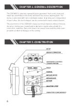
Page 6: ...ce is provided with two controllable output channels each independent of each other An electrode pair can be connected to each output channel The electronics of the ZZAN602 create electrical impulses...

Page 7: ...period of 4 seconds from the control setting value to a value which is 40 less The lower pulse rate will continue for 1 second Then increase linearly over a 4 seconds period to its original value The...

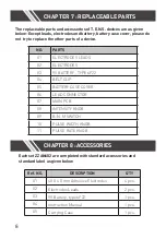
Page 8: ...ECTRODES LEADS 02 ELECTRODES 03 9V BATTERY TYPE 6F22 04 BELT CLIP 05 BATTERY CASE COVER 06 LEAD CONNECTOR 07 MAIN PCB 08 INTENSITY KNOB 09 B N M SWITCH 10 PULSE WIDTH KNOB 11 PULSE RATE KNOB Each set...

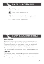
Page 9: ...fibers The choice of which pulse duration to use is partially dependent upon the Treatment Mode and Protocol selected refer to the appropriate section PULSE RATE The Pulse Rate hertz or pulses per sec...

Page 10: ...tion of Conventional TENS and Low Rate TENS In Burst Mode the treatment frequency is fixed by the instrument and is not adjustable with the Frequency Rate control Modulated Mode attempts to prevent ne...

Page 11: ...s see drawing one or two sets of wires may be used After connecting the wires to the stimulator attach each wire to an electrode Use care when you plug and unplug the wires Jerking the wire instead of...

Page 12: ...here If the initial results are not positive feel free to experiment Once an acceptable placement has been achieved mark down the electrodes sites and the settings on the patient s reference sheet of...

Page 13: ...linician has recommended Let this dry Apply electrodes as directed 4 Many skin problems arise from the pulling stress from adhesive patches that are excessively stretched across the skin during applic...

Page 14: ...ectrodes on the liner and remove the lead wire by twisting and pulling at the same time Care and Storage 1 Between uses store the electrodes in the resealed bag in a cool dry place 2 It may be helpful...

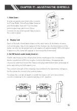
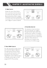
Page 15: ...to a frequency of approximately 30 Hz At higher frequencies the lamp will appear to be constantly illuminated 3 On Off Switch and Intensity Control If both controls are in the off position white mark...

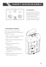
Page 16: ...gh the skin each second By turning these controls the number of current impulses per second Hz for both channels can be continually adjusted Unless otherwise instructed turn the pulse rate control to...

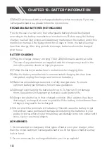
Page 17: ...and remove 3 Remove the battery from the compartment 4 Insert the battery into the compartment Note the polarity indicated on the battery and in the compartment 5 Replace the battery compartment cover...

Page 18: ...acturer s recommended charging time has been completed unplug the charger and remove the battery 4 Batteries should always be stored in a fully charged state To ensure optimum battery performance foll...

Page 19: ...e device and accessories in carrying box and keep it in cool dry place 6 The packed TENS device should be stored and transported under the temperature range of 20 60 relative humidity 20 95 atmosphere...

Page 20: ...if any damage is detected If there is any other problem please return the device to your distributor Do not try to repair a defective device The ZZAN602 devices are in compliance with the EN 60601 1 2...

Reviews: