background image

12

2.2.4 Adverse Reactions

1) Possible skin irritation or electrode burn under the 

electrodes may occur.

2) Possible allergic skin reaction to tape or gel may occur.

3) If the stimulation levels are uncomfortable or become 

uncomfortable, reduce the stimulation intensity to a 

comfortable level and contact your physician if problems 

persist.

4) Patients may experience skin irritation and burns beneath 

the stimulation electrodes applied to the skin.

5) Patients may experience headache and other painful 

sensations during or following the application of electrical 

stimulation near the eyes and to the head and face.

6) Patients should stop using the device and should consult 

with their physicians if they experience adverse reactions 

from the device.

25) Use caution when the patient has a tendency to bleed 

internally, such as following an injury or fracture.

26) Safety of powered muscle stimulators for use during 

pregnancy has not been established.

27) Caution should be used for patients with suspected or 

diagnosed epilepsy.

28) Caution should be used in the presence of the following:

29) When there is a tendency to hemorrhage following acute 

trauma or fracture;

30) Following recent surgical procedures when muscle 

contraction may disrupt the healing process;

31) Over the menstruating or pregnant uterus; and

32) Over areas of the skin that lack normal sensation.

Summary of Contents for ZZACOMBOBDPT2

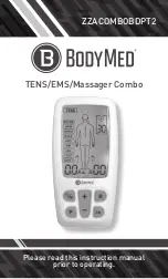
Page 1: ...TENS EMS Massager Combo ZZACOMBOBDPT2 Please read this instruction manual prior to operating...

Page 2: ...2 All Rights Reserved ZZACOMBOBDPT2 Rev 2019 CAUTION Federal law restricts this device to sale by or on the order of a physician...

Page 3: ...ng to Know Your Device 13 4 Specification 15 5 Operating Instruction 19 6 Instructions for Use 23 7 Cleaning and Maintenance 29 8 Troubleshooting 32 9 Storage 33 10 Disposal 33 11 Electromagnetic Comp...

Page 4: ...ogram controls the generated electric impulses their intensity frequency and pulse width Based on simulating the body s natural pulses the mechanism of electrical stimulation equipment is to create el...

Page 5: ...the injured area along the small nerves leading to the spinal cord There the message is transmitted to different nerves that travel up the spinal cord to the brain Then the pain message is interpreted...

Page 6: ...tern it is able to work directly on muscle motor neurons The EMS System has low frequencies and this in conjunction with the square wave pattern allows direct work on muscle groupings 2 SAFETY INFORMA...

Page 7: ...shock burns electrical interference or death 2 The device should not be used when cancerous lesions or other lesions are present in the treatment area 3 Stimulation should not be applied over swollen...

Page 8: ...airway or cause difficulty in breathing or adverse effects on heart rhythm or blood pressure 6 Do not apply stimulation in the presence of electronic monitoring equipment e g cardiac monitors ECG ala...

Page 9: ...e all not on the two large pectoral muscles Here it can increase the risk of ventricular fibrillation and lead to cardiac arrest 15 Never use on the eye area 16 Never use near the genitals 17 Apply th...

Page 10: ...ectrical stimulation or silicone rubber If rash develops or pain persists discontinue use and consult a doctor The irritation can usually be reduced by using an alternate conductive medium or alternat...

Page 11: ...vices 18 Do not use sharp objects such as pencil point or ballpoint pen to operate the buttons on the control panel 19 Inspect applicator cables and associated connectors before each use 20 Electrical...

Page 12: ...the eyes and to the head and face 6 Patients should stop using the device and should consult with their physicians if they experience adverse reactions from the device 25 Use caution when the patient...

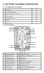
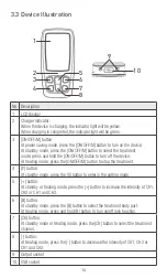
Page 13: ...width symbol 5 Intensity for ChannelA 13 Intensity for Channel B 6 Low battery symbol 14 Symbol of ChannelA 7 Timer symbol 15 Indicator Flag of Channel selection 8 Program symbol 16 Symbol of Channel...

Page 14: ...button to stop the treatment 4 P button At standby mode press the S button to enter in the setting mode 5 button At standby or treating mode press the button to increase the intensity of CH1 CH2 or C...

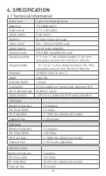
Page 15: ...ion 109 54 5 23mm L x W x T Weight About 76g Automatic Shutoff 1 minute Classification BF type applied part internal power equipment IP22 Size of electrodes pad 50x50mm square Output precision 20 erro...

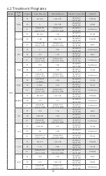
Page 16: ...Adj 5 90 P R M P2 6 8 10 250 Default 30 Adj 5 90 P R M U1 Default 55 Adj 2 100 Default 200 Adj 100 300 Default 30 Adj 5 90 Continuous Abdomen P1 80 120 120 100 Default 30 Adj 5 90 P R W M P2 120 55 D...

Page 17: ...hronous Back P1 60 200 Default 30 Adj 5 90 Synchronous P2 70 200 Default 30 Adj 5 90 Synchronous U1 Default 80 Adj 20 100 Default 200 Adj 100 300 Default 30 Adj 5 90 Synchronous Abdomen P1 20 200 Defa...

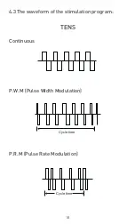
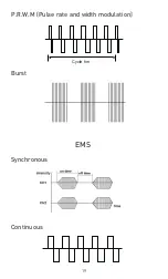
Page 18: ...18 4 3 The waveform of the stimulation program Continuous P W M Pulse Width Modulation P R M Pulse Rate Modulation TENS Cycle time Cycle time...

Page 19: ...19 Burst EMS Synchronous Continuous P R W M Pulse rate and width modulation Cycle tim...

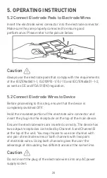
Page 20: ...device Ensure the electrode wires are inserted correctly The device has two output receptacles controlled by Channel A and Channel B at the top of the unit You may choose to use one channel with one...

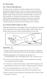
Page 21: ...f treatment according to the instruction of this user manual Please make the skin clean before use and ensure the skin and electrodes connect well 1 Always remove the electrodes from the skin with a m...

Page 22: ...of the individual patient Every patient is differing from the responds to electrical stimulation and their needs may vary from the conventional settings suggested here If the initial results are not p...

Page 23: ...into the standby mode as the picture shown 6 2 Select Treatment Mode Press the ON OFF M button to select which treatment mode TENS MASS EMS you will use The LCD display as follows 6 3 Select Treatment...

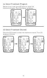
Page 24: ...atment Channel Press the CH button to select the treatment channel The LCD displays as follows 6 4 Select Treatment Program Based on your need press P button to select the treatment program The LCD di...

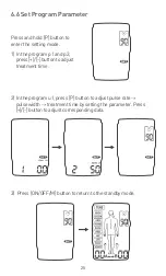
Page 25: ...atment time by setting the parameter Press button to adjust corresponding data 6 6 Set Program Parameter Press and hold P button to enter the setting mode 1 In the program p1 and p2 press button to ad...

Page 26: ...rtable At treating status press and hold B button to turn on lock function The indicator will display on the LCD This is a safety feature to prevent accidental changes to your settings and to prevent...

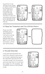
Page 27: ...tor returns to the standby mode 6 9 Stop the Treatment and Turn Off the Device Press the ON OFF M button to stop treatment during the treating mode Press the ON OFF M button again to turn off the stim...

Page 28: ...charging port on the device Connect the USB cable to the charger When the device is charging the indicator light will be yellow It could take up to 2 hours to reach a full charge When charging is comp...

Page 29: ...er or other liquids 7 1 3 The COMBO stimulator is sensitive to heat and may not be exposed to direct sunlight Do not place it on hot surfaces 7 1 4 Clean the surface of the electrode pads carefully wi...

Page 30: ...ed by BodyMed 7 3 3 Inspect your electrodes before every use Replace electrodes if needed Reusable electrodes may cause slight skin irritation lose adhesion and deliver less stimulation when overusing...

Page 31: ...of the protective backing that is labeled with the word 3 It may be helpful to improve repeated application by spreading a few drops of cold water over the adhesive and turn the surface up to air dry...

Page 32: ...eck and re paste it on skin 2 Check the connection 3 Charge 4 Wipe the electrode and the skin with a wet cotton cloth Automatic halt in the treatment 1 The electrode loses connection with the skin 2 I...

Page 33: ...it electrodes lead wires and manual back into the carrying case Store the case in a cool dry place 10C 55C 10 90 relative humidity 2 Do not keep in places that can be easily reached by children 10 DIS...

Page 34: ...ions CISPR11 Group 1 The device uses RF energy only for its internal function Therefore its RF emissions are very low and are not likely to cause any interference in nearby electronic equipment RF emi...

Page 35: ...urst IEC 61000 4 4 2 kV for power supply lines Not applicable Not applicable For INTERNALLY POWERED ME EQUIPMENT Surge IEC 61000 4 5 1 kV line s to line s Not applicable Not applicable For INTERNALLY...

Page 36: ...site survey a should be less than the compliance level in each frequency range b Interference may occur in the vicinity of equipment marked with the following symbol NOTE 1 At 80 MHz and 800 MHz the h...

Page 37: ...DECT LTE Band 1 3 4 25 UMTS Pulse modulation b 217Hz 2 0 3 28 1845 1970 2450 2400 2570 Bluetooth WLAN 802 11 b g n RFID 2450 LTE Band 7 Pulse modulation b 217Hz 2 0 3 28 5240 5100 5800 WLAN 802 11 a...

Page 38: ...sible for waste disposal in your area if any questions Applied part of type BF Refer to instruction manual The first number 2 Protect against solid foreign objects of 12 5 mm and greater The second nu...

Page 39: ...he warranty period either for the device or for the replacement parts 3 The following cases are excluded under the warranty All damages that arise due to improper operation e g nonobservance of the us...

Page 40: ...40 TENS EMS Massager Combo ZZACOMBOBDPT2...

Reviews: