background image

Part List

18

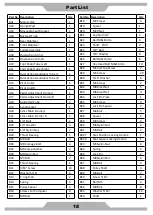
Part No  Description 

Qty 

Part No  Description 

Qty

A01 

Main Frame 

1

B18 

M3 Screw 

4

A02 

Upright Post 

1

B19 

Spacer   

1

A03 

Moveable Seat Bracket 

1

B20 

M20 Nut 

1

A04 

Backrest Tube 

1

B21 

Cap Nut 3/8'' 

2

A05 

Rear Stabilizer 

1

B22 

Bolt M8x16mm 

6

A06 

Front Stabilizer 

1

B23 

Shaft

20 

2

A07 

Saddle Assembly 

1

B24 

3/8" Bolt 

4

A08 

Dual Action Arm /L 

1

B25

3/8" Washer

6

A09 

Dual Action Arm /R 

1

B26 

Bolt M6x15mm 

8

A10 

Foot Pedal Tube /Left 

1

B27 

Hex Head Bolt M8x16mm 

10

A11 

Foot Pedal Tube /Right 

1

B28 

M5 Self Tap Screw 

2

A12 

Dual Action Handlebar Tube /L 

1

B29 

M5 Screw 

29

A13 

Dual Action Handlebar Tube /R 

1

B30 

5/16" Washer 

8

A14 

Picot Link/L 

1

B31 

M5 Screw 

2

A15 

Picot Link/R 

1

B32 

M8 Rivet Nut 

5

A16 

Pedal Adjustment Frame/L 

1

B33 

M6 Rivet Nut 

3

A17 

Pedal Adjustment Frame/R 

1

B34 

Lock Pin Plate 

1

A18 

Guide Rail Tube 

2

B35 

M6 Screw 

3

A19 

Seat Bracket 

1

B36 

Lock Pin Spacer 

3

A20 

Cross Main Frame /L 

1

B37 

M8 Bolt 

5

A21 

Cross Main Frame /R 

 1

B38 

Spacer 

5

B01 

1/4" Bolt 

B39 

M4 Screw 

4

B02 

1/4" Washer 

B40 

M6 Nylon Nut 

2

B03 

1/4" Nylon Nut 

B41 

M5 Bolt 

2

B04 

Thrust Bearing 

 1 

B42Y 

Seat Position Locking Handle 

1

B05 

M8 Bolt 

 4 

B42R 

Seat Swivel Locking Handle 

1

B06 

M8 Carriage Bolt 

 4 

B43 

M5 Nylon Nut 

6

B07 

M8 Curve Washer 

 4 

B44 

Spring 

2

B08 

M8 Nylon Nut 

 4 

B45 

Lock Pin 

2

B09 

M3 Bolt 

 2 

B46 

M8 Nylon Nut 

4

B10 

Thrust Bearing 

 1 

B47 

M8 Bolt 

4

B11 

3/16" Screw 

24 

B48 

Pulley Shaft 

4

B12 

Washer 5/16" 

 4 

B49 

M6 Bolt 

2

B13 

C-ring R-34 

 2 

B50 

Screw 5/16” 

8

B14 

Spring 

 4 

B51 

Bolt M5 

4

B15 

Pulley Spacer 

 4 

B52 

M8 Bolt 

8

B16 

Screws For Computer 

 4 

B53 

Washer 5/16”                                          12

B17 

M8 Bolt 

B54 

Shaft 

1

Summary of Contents for SCT400g

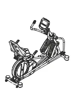
Page 1: ...SCT400g Seated Elliptical Trainer ...

Page 2: ... and the Bodycraft SCT400g will provide an effective workout producing results that will encourage you to reach your fitness goals and maintain the body you have always wanted Spending 15 to 30 minutes a day three times a week is all you need to start seeing the benefits of a regular exercise program As a premium exercise equipment manufacturer we are committed to your complete satisfaction If you...

Page 3: ...Product Safety 1 Parts Drawing Contents 2 Hardware Tools 3 Assembly 4 Troubleshooting Adjustment 9 Stretching 11 Computer Operation 12 Part List 18 ExplodedView 20 Warranty 23 TABLE OF CONTENTS ...

Page 4: ...andle bars To ensure the pedals run smoothly you may need to push or pull on the upper body handlebars first then follow with the leg motion 7 Do not use the equipment outdoors 8 This equipment is for household or light commercial use only 9 Only one person should be on the equipment while in use 10 Keep children and pets away from the product while in use This machine is designed for adults only ...

Page 5: ... Stabilizer Front Stabilizer Handrail L R A07 1Set C10 1PC D01 1PC C07 2PC C08 2PC Saddle Frame Upholstered Backrest Computer Foot Pedal Cushion Pad C21 C22 2Set C14 C15 1Set C35 C36 2Set C23 1PC Handrail Arm Decorative Cover A B Upright Post Decorative Cover Upright Joint Cover L R Water Bottle Holder ...

Page 6: ...n Nut M8 Curve Washer M8x20x1 5T Screw M5x16mm B26 8PC B50 4PC B53 8PC B52 4PC B57 1PC Screw M6 15 mm Screw 5 16 15mm Washer 5 16 16 1 5t Screw M8 16 mm Washer 5 16 x30x2 0T B61 1PC Bolt M8x100mm B11 8PC Screw 3 16 18mm 1PC 1PC 1PC Hex Tool with Phillips Screwdriver 13 14 15mm Allen Key M5 Allen Key M6 ...

Page 7: ...lizer Tube A06 under the bracket of Main Frame A01 with Two 3 8 Bolts B24 Four 3 8 Washers B25 and Two 3 8 Dome Nuts B21 which were removed from step 2 2 Tighten bolts and nuts with the Hex Tool with Phillips Screw Driver provided 3 REAR STABILIZER TUBE INSTALLATION 3 1 Use the Style Foam Block or a block of Wood to lift up the rear of Main Frame A01 3 2 Remove Two 3 8 Screws B24 and Two Washers 3...

Page 8: ...e Foot Pads C05 on the Main Frame A01 as needed to level the Seated elliptical trainer 5 2 The Seated elliptical trainer has to be leveled to prevent from wobble or shaking during the exercise Tighten screws with the Hex Tool with Phillips Screw Driver provided 6 UPPER HANDRAIL TUBE INSTALLATION 6 1 Assemble the Upper Handrail Tube A12 A13 into the Handrail Arm A08 A09 with Two M8 Bolts B06 Two M8...

Page 9: ...the plastic cover of the foam tape under the Cushion Pad C08 and attach the Cushion Pad C08 on Foot Pedal C07 8 3 Repeat the same step to assemble the Left Foot Pedal C07 Tighten screws with the Hex Tool with Phillips Screwdriver provided 9 PIVOT CAPS INSTALLATION 9 1 Assemble the Left Right Pivot Caps A B C35 C36 onto the Right Handrail Arm A15 with Four M5 Screws B11 9 2 Repeat the same step to ...

Page 10: ...to the Upright Post A02 with Two M5 Screws B31 which were removed from step 11 1 Remove Tighten screws with the Hex Tool with Phillips Screwdriver provided 12 COMPUTER INSTALLATION 12 1Remove Four M5 Screws B16 from the bottom of Computer D01 12 2Connect the Hand Pulse Cable D07 and L R Quick Key Cables D10 D11 to all cables that come from the Computer D01 12 3Assemble the Computer D01 onto the pl...

Page 11: ... and Cables D08 to all cables that come from the Saddle Frame A07 14 2Assemble the Saddle Frame A07 to the Moveable Seat Bracket A03 and align the four screw holes to the holes at the bracket of the Moveable Seat Bracket A03 Use Four M8 Bolts B52 and Four Washers B53 14 3Assemble the Backrest Tube A04 to the Saddle Frame A07 and align the four screw holes to the holes at the bracket of the Saddle ...

Page 12: ...out holding onto the contact sensors it is likely the wireless receiver that is the problem Wireless Unusually high low or random numbers in the heart rate display indicate a problem Try moistening the electrodes on the heart rate belt The batteries in the belt may be failing Replace the batteries or the Heart Rate belt The problem may be caused by interference Televisions microwaves wireless alar...

Page 13: ...ng 10 Attention When the Seat Bracket A03 wobbled use a wrench to adjust the gap between the Plastic Pulley C16 and the Aluminum Rail F01 F02 Turn the Pulley Shaft B48 with a wrench counterclockwise with smaller gap ...

Page 14: ...outward Pull your feet as close into your groin as possible Gently push your knees towards the floor Hold for 10 counts Toe Touches Slowly bend forward from your waist letting you back and shoulders relax as you stretch toward your toes Reach down as far as you can and hold for 15 counts Hamstring Stretches Sit with your right leg extended Rest the sole of your left foot against your right inner t...

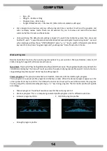
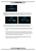
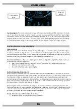
Page 15: ...ich program is selected Except HR programs all other program profiles will follow display rules below There are 20 columns of Dots representing 20 segments of time each segment time total program time divided by 20 columns except Quick Start program which represents 1 minute per column During exercising a column of Dots will blink to indicate the time segment you are currently in and show your wor...

Page 16: ... return to previous activities Basic Operation Power up If this is a self generating product user must pedal the product to power up the console Pause a program If a program is running and there is no RPM for 10 seconds the console will pause and stop accumulating data The pause time is 3 minutes After that the console will reset back to idle mode Within pause mode pedal again to resume the progra...

Page 17: ...Interval Hill Climb Strength Target HR HR Interval and Custom Quick Start Pressing GO keyduringidlemodewillquickstarttheconsole Theprogramwillusefactory defaults for calculation and display The time will count up and each segment of progress profile equals 1 minute Youmay stoppedalingatanytimeorpress Home keytoendtheprogram Classic programs This group includes Manual Random Intervals Hill Climb St...

Page 18: ...t is set at 70 max HR calculated as 220 Age You may also press 5 6 key to adjust the target heart rate setting during heart rate control session of the exercise HR Interval program profile There are two phases of this training Work Interval and Rest Interval After warm up the console will take the default target setting to begin Work interval and adjust the resistance automatically When the target...

Page 19: ...e that the palms of the hands are touching the contact area of each hand pulse grip Maintain an even pressure on the grips Do not hold the hand pulse grips too tightly Built in Wireless Heart Rate Receiver Note Chest strap transmitter does not come with this unit contact BODYCRAFT or your dealer for purchase This product is equipped with a built in receiver for your heart rate monitoring Any heart...

Page 20: ... body This amount of exercise is between 60 and 85 of your maximum heart rate measured during a training session This range allows enough exercise to achieve fitness but not an excessive amount to cause injury Your heart rate is an excellent indicator of the amount of stress placed on the cardiovascular system If exercise intensity is too low or too high no gains will be made in fitness If the int...

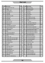
Page 21: ... Nut 5 A16 Pedal Adjustment Frame L 1 B33 M6 Rivet Nut 3 A17 Pedal Adjustment Frame R 1 B34 Lock Pin Plate 1 A18 Guide Rail Tube 2 B35 M6 Screw 3 A19 Seat Bracket 1 B36 Lock Pin Spacer 3 A20 Cross Main Frame L 1 B37 M8 Bolt 5 A21 Cross Main Frame R 1 B38 Spacer 5 B01 1 4 Bolt 2 B39 M4 Screw 4 B02 1 4 Washer 4 B40 M6 Nylon Nut 2 B03 1 4 Nylon Nut 2 B41 M5 Bolt 2 B04 Thrust Bearing 1 B42Y Seat Posit...

Page 22: ...y R Cable UP DOWN 1 C08 Cushion Pad 2 D07 Hand Pulse Sensor Cable I 1 C09 Belt 1 D08 Hand Pulse Sensor Cable II 1 C10 Upholstered Backrest 1 D09 Hand Pulse Sensor Cable III 1 C11 Upright Tube Spacer 2 D10 Quick Key Cable L 1 C12 Plug 5 D11 Quick Key Cable R 1 C13 Rubber Grip 2 D12 Motor Tension Cable 1 C14 Upright Post Joint Cover Right 1 D13 Control Board Cable 1 C15 Upright Post Joint Cover Left...

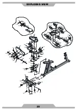
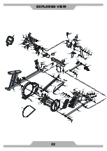
Page 23: ...B50 B50 B52 B53 B53 B52 B52 B53 B53 C10 C12 C29 B61 B57 B08 B54 C34 C34 B45 B49 B42R B41 B40 C17 B44 B43 B22 B22 B22 A19 B63 B04 B62 B30 E03 B30 B30 B30 B15 B15 B15 B15 B49 B48 B48 B47 B47 E03 E03 E03 E03 E03 E03 E03 E03 E03 E03 E03 E03 E03 E03 E03 B08 B45 B44 B43 B42Y B41 B40 A03 C16 C16 C16 C16 C16 C16 C16 C16 C17 EXPLODED VIEW 20 ...

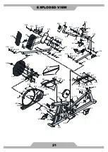
Page 24: ...B33 B33 B32 B32 C18 F02 C18 B39 B39 B38 B38 B37 B37 B32 B32 F01 C18 D09 C19 C19 B29 B29 E02 C20 B30 B22 B13 B29 B09 E01 C32 B27 B12 E01 B55 A18 B27 B57 B57 B27 A08 A10 A12 A14 A16 C07 B58 D05 C33 C21 C22 C32 C32 B29 B08 B07 B06 E02 C32 B27 B12 E02 B11 B56 C34 C26 B27 C26 B08 D04 B52 B26 D16 D13 D08 F03 C35 C36 C08 B58 D15 C31 C31 B14 C31 C31 B14 B53 B53 B23 D14 B29 C12 C12 F04 B43 B51 C37 C34 ...

Page 25: ...C04 C04 C05 C05 B09 C33 A13 A09 B56 B12 B27 E02 B13 C20 B30 B22 E02 B29 B55 C15 C14 B29 A18 C12 B58 B27 B57 B58 C26 B52 B26 C26 A11 A15 B11 B27 B05 B05 A17 B08 B16 C07 D01 C21 C22 C32 C32 C32 B29 B08 B07 B06 B27 B30 C24 C25 E02 C27 C26 E02 B12 B27 C32 E01 C34 E01 D07 F03 C34 C35 C36 C08 C31 C31 B14 C31 C31 B14 B53 B23 C12 F04 B43 B43 B51 B57 B27 ...

Page 26: ...Memo ...

Page 27: ...Memo ...

Page 28: ...ent misuse water tampering unreasonable use unauthorized repairs improper repairs alterations or normal wear and tear This warranty excludes the following 1 The warranty does not cover normal maintenance or labor charges unless labor terms are listed above 2 Normal cosmetic wear on parts such as paint seat coverings walk belts pedal straps wheels foot rails labels and logos 3 Consumables such as b...

Page 29: ......

Reviews: