R1
R4
R2
R5
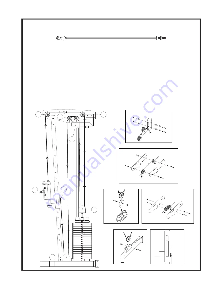
STEP 5 Top Cable Assembly
TOP CABLE (416)
R1
419
416
419
411
430
430
430
441
438
438
438
432
R6
R3
R2,R3
441
419
R2
432
438
419
438
441
438
432
405R1
405R2
438
R3
R8
R7
R5,R6
438
438
419
441
438
438
405R1
405R2
432
R6
R5
8
R8
407R
R7
441
401R
419
434
R4
419
417
409
434
441
Assemble cables and pulleys simultaneously.
※
Pulleys are mounted using 3/8" X 3" Hex Bolts (432), 3/8" Washers (438), and 3/8" Nylon Nuts
(441). Pay attention, as some places use washers, others don't.
1. Insert the threaded end of the Top Cable (416) between the pulleys in the front of the Right Cable
Height Adjuster (407R) as shown Fig. R1. Route the cable up and over two top Pulleys at the
Front and Rear of the Top Panel (405) as shown Fig. R2 & R3, then down to the Pulley Bracket
(409) as shown Fig. R4.
2. Continue routing over the two lower pulleys on the Top Panel (Fig R5 & R6) and then down to the
pulley in the welded bracket on the Right Base Frame (401R) as shown in Fig R7. Screw the
threaded end of the Top Cable (416) into the Bracket welded on the Right Cable Height Adjuster
(407R)
AT LEAST
one third of the way. This is a cable adjustment area. When all cables have
been tightened, make sure to secure the Jam Nut to prevent the Top Cable (416) from
unscrewing.


