


HEC Series
37
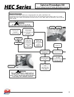
Service Procedure VIII
Flame Sensor Testing & Replacement
With flame sensor Disconnected
from ignition module, check
continuity to ground.
Is there continuity to ground?
N
Y
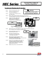
Flame Sensor Testing Procedure
Refer to illustration below, is there
a minimum of 1 micro amp during
1.5 second flame proving period?
Y
N
Is flame sensor free
of oxidation?
Clean or replace
flame sensor.
(see “Flame Sensor
Replacement
Procedure”)
N
Is ceramic of flame
sensor cracked?
Replace flame sensor.
(see “Flame Sensor
Replacement
Procedure”)
Y
N
Flame sensing circuit OK
Y
Refer to ignition module/control board
illustration.(24 volts should maintain beyond the
1.5 second flame proving period.)
Is there 24 volts AC at locations
P3(2)
&
P3(5)
?
Y
N
Call for
technical support
Replace flame sensor with
gasket
and/or wire lead.
(see “Flame Sensor
Replacement Procedure”)
Remove flame sensor from water heater.
Check continuity from tip of flame sensor
to end of wire lead.
Is there continuity?
N
Y
WARNING
1
20 volt potential exposure. Use caution
m
aking voltage checks to avoid
personal injury. Flame sensor may be
too hot to handle, take necessary
precautions
Flame
sensor
terminal
Volt meter set to
Micro amps setting
( A)
Meter
probe
Meter
probe
Flame sensor
terminal on
ignition module.
P2
P3
P5
P1
P7
Summary of Contents for 100-HEC399
Page 59: ...HEC Series 59 Notes NOTES ...


