Design and function
TIG welding
099-002050-BOC01
30.11.2009
23
5.7.1.3
Shielding Gas Supply
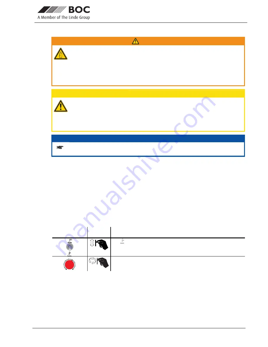
WARNING
Incorrect handling of shielding gas cylinders!
Incorrect handling of shielding gas cylinders can result in serious and even fatal injury.
• Observe the instructions from the gas manufacturer and in any relevant regulations
concerning the use of compressed air!
• Place shielding gas cylinders in the holders provided for them and secure with fixing
devices.
• Avoid heating the shielding gas cylinder!
CAUTION
Faults in the shielding gas supply.
An unhindered shielding gas supply from the shielding gas cylinder to the welding torch
is a fundamental requirement for optimum welding results. In addition, a blocked
shielding gas supply may result in the welding torch being destroyed.
• Always re-fit the yellow protective cap when not using the shielding gas connection.
• All shielding gas connections must be gas tight.
NOTE
Before connecting the pressure reducer to the gas cylinder, open the cylinder valve
briefly to expel any dirt.
• Tighten the pressure reducer screw connection on the gas bottle valve to be gas-tight.
• Tighten gas hose on pressure reducer to be gas tight.
•
Slowly open the gas cylinder valve.
•
Open the rotating valve on the welding torch
Before each welding process, the rotating valve must be opened; after the welding process, it
must be closed.
•
Set the required amount of shielding gas on the pressure reducer, about 4 - 15 l/min depending on the
current strength and the material.
Rule of thumb for gas flow rate:
Diameter of gas nozzle in mm corresponds to gas flow in l/min.
Example: 7 mm gas nozzle corresponds to 7 l/min gas flow
5.7.2
TIG welding selection
Operating
Element
Action Result
TIG
welding process selected
20
40
60
80
100
120
140
160
AMP
Main current setting


