background image

26

◆ Press

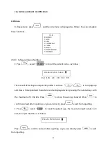
,select“2.SEX”to input patient sex, the interface is as follow:

Use number key

to select“1.MALE”,press

to select“2.FEMALE”。

◆ Press

,and select“3.COMMENT”to enter Image Note. White cursor will appear

on the screen, together with 26 letter keys and space key at the bottom.

and

are used to turn page up and down. Corresponding characters can be displayed

when pressing the number key, with the maximum of 15 letters. Press

to clean the

wrong character. Press

to confirm and exit after inputting, or you can directly

press

to exit from inputting.

◆Press

,and select“4.TIME”to modify time and date. The interface is as follow:

For example:2014-9-22 9:35:30 are input as follow:

Press

to confirm and exit after inputting, or you can directly press

to exit

from inputting.

◆ Press

,and select“5.HOSP”to input hospital name,as follow

0-A 1-B 2-C 7-D 8-E 9-F

You can refer to patient input for details. There is a maximum of 16 characters in the name.

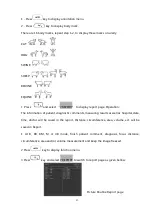
◆Press

key to select body mark, Operation:

PLEASE ENTER SEX:

1. MALE

2.FEMALE

YY-MM-DD

HH-MM-SS

YY-MM-DD

140922

HH-MM-SS

093530

PLEASE ENTER HOSP:

Summary of Contents for FarmScan L60

Page 1: ...FarmScan L60 The Versatile Ultrasound machine for small and large animal scanning User Guide BMV1956 C English P N No MX30 02463 Release date June We specialize because you do ...

Page 2: ...755 26564580 Fax 00852 2851 0669 www bmv cc Email info bmv cc If you have comments about the documentation please write to us at the email address above We would like to hear from you BMV Technology Customer Satisfaction Input from our customers helps us improve our products and services As part of our customer satisfaction program we contact a sample of our customers a few months after they recei...

Page 3: ...g through auto charger 16 1 7 Battery Operation 17 Charter 2 Operation Sequence 18 2 1 Screen Display 18 2 2 Keyboard Functions 18 2 3 Power on 22 2 4 Diagnose 22 2 5 Modify Image Parameters 23 2 5 1 Frequency Setting 23 2 5 2 Focus settings 23 2 5 3 Frame correlation settings 23 2 5 4 Image Smoothen 24 2 5 5 Gamma correction 24 2 5 6 Gain Setting 24 2 5 7 Modify Brightness and Contrast 24 2 5 8 P...

Page 4: ...ge upload to computer 44 2 14 Power Off 44 Chapter 3 Troubleshooting and Maintenance 45 3 1 Troubleshooting 45 3 2 Service life 45 3 3 Check 45 3 4 Main unit maintenance 46 3 5 Probe maintenance 46 3 6 Cleansing 47 3 7 Correct usage of probe 48 3 8 Battery information 48 3 9 Instrument test and calibration 50 3 10 Maintenance of THIS EQUIPMENT Veterinary Ultrasound Scanner 50 Basic content of main...

Page 5: ...aration of Conformity DoC is on our website Execution Standard Safety Standard Number Standard Name EN60601 1 Medical Electronic Device Part I General safety requirements IEC60601 1 2 2007 Medical Electronic Device Part I to II General Safety Requirement Parallel Standard Requirement and Testing of Electromagnetism Compatibility IEC60601 1 4 2000 Medical Electronic Device Section I to IV A Program...

Page 6: ...ecific information about peripherals Customer comments Questions and comments are encouraged BMV Technology Co Ltd is interested in your feedback regarding the system and the user guide You can call the nearest manufacturer s representative You can also e mail BMV Technology Co Ltd at info bmv cc Conventions The user guide follows these conventions WARNING A WARNING label applies to information th...

Page 7: ...use slight personal injury or property damage Note to remind user of installation operation or maintenance information These information is very significant but with no risk Any warning against dangers shall not be contained in NOTE Safety labels Device labels explanation Attention consult accompanying documents Switch on the main electrical supply Switch off the main electrical supply AV Signal o...

Page 8: ...rpose of selling or making benefit We preserve the right of revision on this document without still further notice Some pictures in this manual which are schematic diagrams for indication only may disaccord with the real object and then the real object should be regarded as the final Manufacturer s warranty Our company assumes the responsibility for device security reliability and performance only...

Page 9: ...are not free either Our company shall not be responsible for damages caused by other devices or arbitrary connection to other devices Our company shall not be responsible for losses damages or injuries caused by delayed service request When there is problem with the products please contact our company and explain the device model serial number date of purchase and the problem BMV Pro Support servi...

Page 10: ...armScan Wipe display gently with a lint free cloth Cleaning cloth and cleaners for glasses sunglasses work well Care should be taken not to scratch the screen Video cap or goggle must be plugged in at all times during cleaning so water does not enter the scanner Store in a dry environment Corrosion will occur if stored damp How do I get my ultrasound machine repaired Where do I ship my ultrasound ...

Page 11: ...not a set schedule for upgrades Upgrades are completed when your item is in for service Most upgrades just enhance the functionality of the unit If an upgrade is needed because of a serious problem we will contact those customers that need the upgrade individually and get the units in for an upgrade immediately Can I leave my ultrasound machine outside in the cold While in use your ultrasound mach...

Page 12: ...ip it We recommend shipping via an air freight company that provides you with a tracking number We typically do not insure packages that is at your discretion 4 Repair returned We aim to complete your repair and return your system as soon as possible As soon as we receive your equipment in our BMV service center 99 of our repairs are completed and shipped back within 48 hours This lessens the need...

Page 13: ...ansportation environment Environmental requirements on normal operation a Environment temperature range 5 40 b Relative humidity range 30 80 c Atmosphere pressure range 700hPa 1060hPa Environment requirements on device storage and transportation a Environment temperature range 5 40 b Relative humidity range 80 20 7 Do not hit the fragile TFT LCD display If it cracks deal carefully with it in case ...

Page 14: ... the adapter to reduce risk 12 Our company shall not take any responsibility for any risk resulted from propelled unauthorized re fitment by the users 13 To disconnect the device from the power supply network by unplug the adapter from the power supply network 14 Ultrasound might cause hazard on human body so long time radiation should be avoided Refer to appendix A for sound output parameters ...

Page 15: ... Scan video glasses eases your job and gets you focused optional I F R introducer engineered to lessen fatigue and stress by allowing arm free scanning use in a variety of reproductive diagnostic procedures optional compatible with the Rectal convex and Rectal Linear transducers Advance Features Only weight 0 6 kg Excellent imaging quality and ergonomic design Provides versatile solutions with the...

Page 16: ...ts on side 4 Handle 5 Kickstand 6 Cool Fan Out 7 Battery compartment 8 Cool Fan In 1 2 EMC statement FarmScan L60 can t affect the basic performance of radio service and other equipment and can work well in the expected and declared electromagnetic environments Warning Working in intense electromagnetic environment its images may be interfered and the diagnoses may be affected By this time stop op...

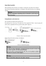
Page 17: ... scanner The probe is very important part of the scanner because of its sensitive mechanism it is important to be careful and protect the probe from falling or hitting 1 3 Range of application Suitable for all veterinary applications bovine beef bovine dairy Lama and small ruminants swine ovine pets such as dogs and cats 1 4 Preparing the system Operating environmental requirements 1 Environment t...

Page 18: ...e probe jack lies in the top of the right side of the equipment There is only one plug jack which is also compatible for those optional probes refer to figure 1 Picture 1 Probe connection sketch Dismounting is the reverse process of installation Picture 2 Disassemble probes Warning Avoid by all means unplugging or plugging the probe connector at state of log on in case the probe and main unit be d...

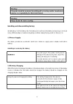
Page 19: ...ing the battery WARNING To avoid injury to the operator and to prevent damage to the ultrasound system inspect the battery for leaks prior to installing To avoid data loss and to conduct a safe system shutdown always keep a battery in the system 1 6 Battery Charging When the main unit displays the battery in the empty status in the right top corner of the display screen it indicates that the batte...

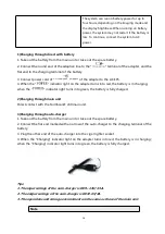
Page 20: ...n charging when the indicator light turns into green the battery is fully charged 2 Charging through main unit Direct contact with the FarmScan L60 main unit 3 Charging through auto charger 1 Take out the battery from the main unit or take out the spare battery 2 Connect the flat end marked with an arrow of the auto charger to the charging terminal of the battery 3 Plug the other end of the auto c...

Page 21: ...ush down the main unit power switch to power on the main unit the power indicator will turn on 3 The device can start operation Note When the main unit under voltage indicator turn into red it means the battery is running up and needs charging Warning It is prohibited to use any other power supply except the standard adapter as the external power supply for the main unit ...

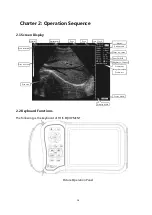
Page 22: ...llowing is the keyboard of THIS EQUIPMENT Picture Operation Panel Patient name Probe modle Scan area Display depth Hospital P age P sex Date Clock Focus no space Gamaconr Image Smoothen Frame rate Brightness Contrast Near Far field Freeze mark Gray level bar Scan direction battery ...

Page 23: ...enter the corresponding sub0menu Refer to the following chapter for further details and press to quit Zoom key In the state of real time scanning press it to alter the image multiple The range is 80 220 with 8 levels Measure Mark Press it in Freeze state then will be displayed on the screen Use direction keys or mouse to move it Refer to next chapter for further details Direction Keys They are use...

Page 24: ...e B mode There are two B picture on the screen One is Freeze picture the other is Real time one Repeat pressing the picture can shift between Freeze and Real time Press then both of them show freeze picture B and M Mode Display At real time or freeze state press this key to enter B M mode B mode and M mode images will be displayed simultaneously on the screen BM or B M for short B mode real time i...

Page 25: ...it please press Measure Reference Along with and direction keys the measure of distance perimeter area volume and histogram can be done Further details are available in the following chapter Press it the note menu is displayed Then press the number keys to enter the sub menu Refer to the following chapter for further details Press to exit Clean Screen Press it to clean marks notes and results In m...

Page 26: ...e may be damaged by overheat 2 4 Diagnose Spread medical sonic couplant on diagnostic area and attach the probe sound window closely to it The ultrasound image of the tissue section will be displayed on the screen Move the probe and find out the right place Adjust the gain to maintain the best image Attention 1 Excessive force is not allowed while the probe touching diagnostic area for it may dama...

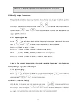
Page 27: ...ies of each probe are LR65 5 5MHz 6 5MHz 7 5MHz C350 2 5MHz 3 5MHz 5 0MHz 3 5MHz Convex probe C520 4 5MHz 5 0MHz 5 5MHz 5 0MHz micro convex probe LH75 6 5MHz 7 5MHz 8 5MHz 7 5MHz HF linear probe Note In the acoustic output table the probe s working frequency is the frequency corresponding to highest acoustic output 2 5 2 Focus settings Press or to lighten up FPIN on up right screen and press to mo...

Page 28: ...ng At real time press or to lighten GAIN NG FG in the upper right hand corner and use and to adjust 2 5 7 Modify Brightness and Contrast Press or to lighten and use and to modify the brightness and contrast 2 5 8 Probe Setting The device can automatically identify probes There are 4 probes are available with this device The current probe type displays on the upper right screen and the probe type a...

Page 29: ...n Correspondant characters can be displayed when pressing the number key with the maximum of 15 letters Press to clean the wrong character Press to confirm and exit after inputting or you can directly press to exit from inputting Press select 1 AGE to input the patient age the maximum input number is 3 bits the input interface is as follow Press to confirm and exit after inputting or you can direc...

Page 30: ...ong character Press to confirm and exit after inputting or you can directly press to exit from inputting Press and select 4 TIME to modify time and date The interface is as follow For example 2014 9 22 9 35 30 are input as follow Press to confirm and exit after inputting or you can directly press to exit from inputting Press and select 5 HOSP to input hospital name as follow 0 A 1 B 2 C 7 D 8 E 9 ...

Page 31: ...of patient diagnostic comments measuring results as well as hospital date time doctor will be saved in the report Distance circumference area volume ect will be saved in Report 1 At B BB BM M or 4B mode finish patient comment diagnosis focus distance circumference area and or volume measurement and keep the image freezed 2 Press key to display function menu 3 Press key and select 7 REPORT to switc...

Page 32: ...r 2 7 1 Cineloop playback There is 400 images cineloop playback or single frame review function Start the system and enter real time state first capture images for cineloop about 30 seconds 1 Freeze the image Press to display image process menu and then press to start playback 2 During playback press or keys to enter manual play mode Press key to go to the next image and press key to go back the p...

Page 33: ...erase No 01 Press to replace Press to abandon the storage of the current image Select 2 NO to abandon the current storage In the later storing operation there will be hint for whether to erase No 02 The process continues Notes If the storage is full and at this time you pick out certain image to store it There will be hint for whether to erase the existed one of specific number and store the new o...

Page 34: ...age Repeat the above steps to flip image up and down Image up and down flip 2 7 5 Image left right flip At real time press key to display function menu Press to change scan direction of the probe Repeat the above steps to flip image left and right Image left and right flip Probe scan direction sign in the red circle is the left and right flip sign The default scan direction is given as the left im...

Page 35: ...he first one is Freehand method and the second is Ellipse method a Freehand Keyboard Operation 1 Press to select Freehand method Then measure cursor appears on the screen Use direction keys to move the cursor to the start of the examined spot 2 Press and use direction keys to move the cursor along the fringe of the examined area to the end 3 Press again to finish the measuring If measuring should ...

Page 36: ...pot of the examined area 2 Press right button to move the cursor along the fringe of examined area to the end 3 Press right button again to complete the measuring of perimeter and area If measuring should be continued press and or directly press and repeat Step 2 3 You can get 2 groups of data at most The results are on the right side of the screen After the measuring press Middle button to clean ...

Page 37: ...fted into Move the Examined Area 5 After the location size angle of the examined area are confirmed the measuring can be done If measuring should be continued press and or directly press and repeat Step 1 5 You can get 2 groups of data at most The results are on the right side of the screen Picture Illustration of Measuring perimeter and Area Ellipse Method C1 and A1 are respectively perimeter and...

Page 38: ...nfirmed the measuring can be done If measuring should be continued press and or directly press and repeat Step 1 5 You can get 2 groups of data at most The results are on the right side of the screen After measuring press the middle button to clean the screen Volume measuring is in the later chapter 2 7 8 Statistics of Histogram Press in freeze mode the menu is displayed on the screen Press to sel...

Page 39: ...when ERASING exists other operations are not allowed for they may damage the device 2 7 10 Output format of video Press and select 7 PALD NTSC to change the output format of video as the following dialog box shows Press key to select PALD and key to select NTSC 2 7 11 Restore factory settings Press 2 button in real time scanning mode The total gain the near field far field and brightness values wi...

Page 40: ...t button and the cursor is displayed 2 Use the mouse to move the cursor to the starting spot 3 Press the right button to confirm the starting spot 4 Use the mouse to move and another cursor appears cursor of the ending spot Move it to the ending spot and press to complete the measuring Notes Repeat pressing the right button can shift between the beginning spot and the ending spot of the cursor If ...

Page 41: ...cross section by means of distance measuring 3 Measure the diameter of the longitudinal section by means of distance measuring 4 Press to complete the measuring with the value of volume in Vm1 on the right side as follow Illustration of volume measuring 3 Axis Method 2 Measure two groups of perimeter and area by Ellipse Method and obtain the result by calculating Procedures Kidney as example 1 Cat...

Page 42: ...e GA GW can be acquired after measuring GS BL HL SL USD HD BD CRL etc among them the EDD of cat and dog will be given Operation process Freeze the image press key to display equine bovine swine sheep OB menu Press key again to display cat and dog OB menu press key to switch between this two menus as the following figure shows Input the number and select the related OB menu and acquire the distance...

Page 43: ...und to acquire a better observation on the joint of uterine horns and body and then switch the probe to uterine horns as the following figure shows Probe position for uterine and ovaries examination 5 The measurement method of GS diameter is given below and measurement can be done horizontally or vertically Equine GA measurement 6 Confirm the distance value as per distance measurement methods and ...

Page 44: ...f uterine horns and body and then switch the probe to uterine horns as the following figure shows Probe position for uterine and ovaries examination 5 To measure the fetus body diameter select a vertical section first that is a section from two side to the neck chest and abdomen Body diameter can be acquired when the GA is between 60 to 150 days The measurement method of ody diameter is given belo...

Page 45: ...against the abdomen side center shift it a little bit left or right and hold it closely against the skin Clean the abdomen skin if there is mud to ensure a clear display of the abdominal pelvic structure 3 The maximum vertical axile of the heart should be displayed on the screen With the time going on fetus heart long axile increases regularly The measurement method is given below Picture Bovine h...

Page 46: ...ng to hilum spine length of sheep There are two methods to exam pregnant sheep Use convex or linear probe to check abdomen and endo rectal probe to rectum These two methods are the same useful It is proofed as cording to some publication that these two methods are the same effective in pregnancy examination Rectum examination is more exact than abdomen examination within first 35 days pregnancy Th...

Page 47: ... ultrasonic examination The measuring method is 1 Fetal head axial plane scanning look for BPD measuring standard plane from top to bottom 2 According to distance measurement method to measure distance of selected parameters the corresponding gestation age data will automatically show behind G A DOG GSD Calculate the gestation age according to dog gestation saccus diameter The method is the same a...

Page 48: ...evice and operate according to the instructions of video printer 2 13 Image upload to computer Connect the device and the computer with USB cable the high speed USB2 0 port can transfer the image to computer at a high speed 2 14 Power Off Press Power on the right side to turn the device off Notes There is still some power consumption in power off state If the device will not be used in a long time...

Page 49: ...Clear the screen optical filter 3 2 Service life Bases on the manufacturer s design production related files this model s use life is six years The Product s material will gradually aging if the product continually use over the designed use life it may bring the problem of the performance reduced and fault rate raise Note The Discard the device according to local law Do not discard it mixing with ...

Page 50: ...ransportation and storage Environment temperature range 20 55 Relative humidity range 80 200 C Transportation Signs on the packing box conform to Iconograph and sign of packing storage and transportation GB T191 2008 Simple shockproof establishment is fitted within the box which apply to aviation railway highway or steamship transportation Keep dry avoid inversion and collision Storage Equipment s...

Page 51: ...ent feel uncomfortable 3 6 Cleansing 1 When the enclosure need cleaning wipe it with soft dry cloths and then wipe gently with sponge dipped with 75 medical alcohol R50 3 5MHz Convex probe protection Against water ingression sketch map R20 5 0MHz Convex probe protection Against water ingression sketch map 7 5MHz HF linear probe protection Against water ingression sketch map R13 6 5MHz endo vaginal...

Page 52: ...id Do not leave any detergent on the device surface Though there will be no chemical reaction between the device enclosure and most of those detergents We still suggest no detergent in cleaning lest the device surface is spoiled 3 7 Correct usage of probe In order to prolong probe s service life and obtain optimum performance follow these instructions 1 Periodic inspection on probe cable socket an...

Page 53: ... go on using non serviceable battery and electricity charger AC adapter 8 Don t try demounting battery 9 Don t short circuit the battery 10 Do not throw the battery into the fire or heat it otherwise it would trigger an explosion 11 Do not souse or wet the battery 12 Do not incorrectly connect the positive and negative polarity 13 Do not directly connect the battery to wall outlet or car lit socke...

Page 54: ...oth operators and engineers This section will introduce basic items methods and matters need attention during maintenance Basic content of maintenance 1 Periodically clear up dust dirt and humidity inside and outside the equipment according to operating ambient and sanitary conditions 2 Observe circuits closely to check if there is any abnormity or spoiled components analyze and remove the abnorma...

Page 55: ...e humidity in spring and torridity in summer and autumn will cause adverse effect on the equipment easily 2 Daily simple maintenance can be done by operators but inboard maintenance should be charged by engineers with the assistance of operators Must not open the cover and start maintenance without instructions 3 During inboard maintenance it is strictly prohibited to power on the equipment Please...

Page 56: ...d TI need not be provided if the equipment meets both exemption clauses given in 51 2 aa and 51 2 dd Index label MI TIS TIB TIC Scan Non scan Non scan Aaprt 1cm2 Aaprt 1cm2 Maximum index value 0 507 0 043 Note Associated acoustic parameters Pra MPa 1 170 P mW 6 8 Min of Pα zs Izpta αzs mW Zs cm Zbp cm Zb cm Z at max Ipi α cm 2 30 deq Zb cm fawf MHz 5 331 5 331 Dim of Aaprt X cm 4 00 Y cm 0 90 Othe...

Page 57: ... TI need not be provided if the equipment meets both exemption clauses given in 51 2 aa and 51 2 dd Index label MI TIS TIB TIC Scan Non scan Non scan Aaprt 1cm2 Aaprt 1cm2 Maximum index value 0 463 0 063 Note Associated acoustic parameters Pra MPa 0 799 P mW 27 3 Min of Pα zs Izpta αzs mW Zs cm Zbp cm Zb cm Z at max Ipi α cm 3 80 deq Zb cm fawf MHz 2 982 2 982 Dim of Aaprt X cm 6 16 Y cm 1 45 Othe...

Page 58: ...d TI need not be provided if the equipment meets both exemption clauses given in 51 2 aa and 51 2 dd Index label MI TIS TIB TIC Scan Non scan Non scan Aaprt 1cm2 Aaprt 1cm2 Maximum index value 0 349 0 042 Note Associated acoustic parameters Pra MPa 0 732 P mW 6 3 Min of Pα zs Izpta αzs mW Zs cm Zbp cm Zb cm Z at max Ipi α cm 2 80 deq Zb cm fawf MHz 4 389 4 389 Dim of Aaprt X cm 3 12 Y cm 1 00 Othe...

Page 59: ... Equine Measurement mm Week Day Gestational Sac Diameter 6 1 4 8 1 4 10 1 5 12 1 6 14 1 6 16 2 0 18 2 0 20 2 1 22 2 2 24 2 3 26 2 5 28 4 1 30 4 2 32 4 3 34 4 4 40 5 0 42 5 2 44 5 3 46 5 4 48 5 5 50 5 6 52 6 1 54 6 2 56 6 3 All measurements 3 days ...

Page 60: ...56 Gestational Table 2 Bovine Measurement mm Week Day Body Length 8 4 0 10 5 0 12 5 1 14 5 2 16 5 3 18 5 5 20 5 5 22 5 6 24 5 6 26 6 1 28 6 1 30 6 1 32 6 2 34 6 3 36 6 3 All measurements 3 days ...

Page 61: ...to Spine Distance 15 7 1 18 7 3 21 7 6 24 8 1 27 8 4 30 9 0 33 9 2 36 9 4 39 10 0 42 10 2 45 10 5 48 11 3 51 11 5 54 12 1 57 12 2 60 12 4 63 12 6 66 13 2 69 13 4 72 14 2 75 14 4 78 15 0 81 15 2 84 15 5 87 16 6 90 17 0 93 17 1 96 17 3 99 17 6 All measurements 3 days ...

Page 62: ...58 English BMV1956 C6884 Version June 2009 2015 BMV TECHNOLOGY CO LIMITED All Rights Reserved We specialize because you do ...

Reviews: