background image

11 


which can be adjusted  between  4 seconds  to  99 seconds.  Herein, to  press 

  or 

  key  to  change the retaining 

time and press ENTER to confirm the selected value.   

(7) When the cursor comes to the item “Magnification”, press ENTER to preset the magnification ratio which can 

be changed over between Auto, 1X and 2X. Herein, to press 

  or 

  key to select the expected magnification 

ratio and press ENTER to confirm the selection.   

If “Auto” is selected, the magnification ratio will be changed over automatically. If others are selected, the selected 

magnification ratio must be the same as that actually used. Otherwise, the measured results are incorrect.   

(8) When the cursor comes to the item “Test force”, to press ENTER and preset the test forces by pressing 

  or 

  key  from  the  following:  187.5kgf,  250kgf,  500kgf,  750kgf,  1000kgf,  3000kgf.  At  the  end,  press  ENTER  to 

confirm the selection. 

(9) When the cursor comes to the item “Diameter”, to press ENTER and preset the diameter of indenter by pressing 

  or 

  to choose from 

φ

10mm, 

φ

5mm and

φ

2.5mm, and press ENTER to confirm the selection.   

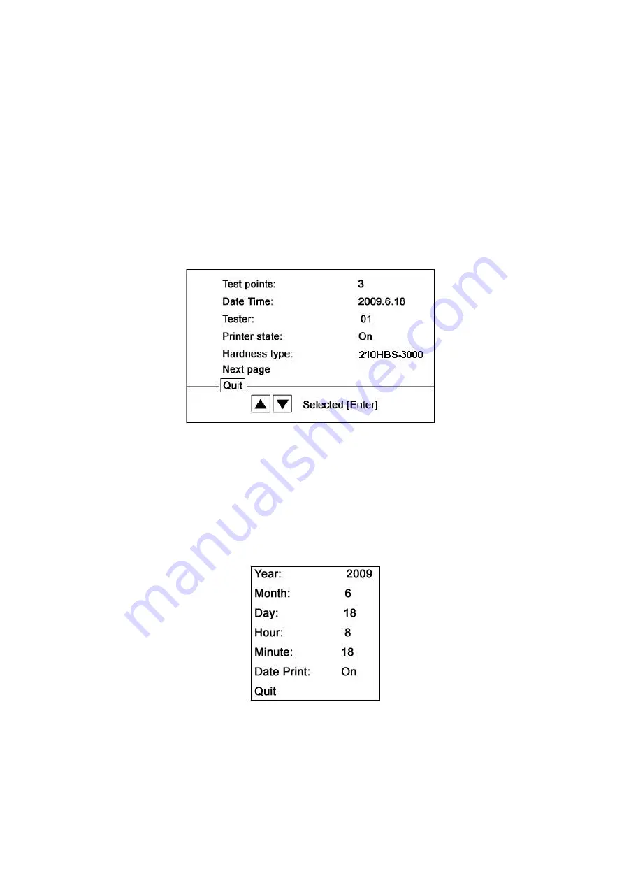
(10) When the cursor comes to the item “Next page”, press ENTER to enter the menu shown in Fig-10. 

(11) When the cursor comes to “Quit”, to press ENTER to exit the preset menu and return to the interface of Fig-8.   


Fig-10 Menu interface 

(12) When the cursor comes to the item “Test points”, to press ENTER to preset whether or not to carry out data 

statistics whose range is from 1 to 99. If 1 is selected, no statistics will be done, i.e. to print out the test results of 

each test. If the figure more than 1 is selected, it will print out the test results of each test and the average of the test 

results. The number of statistical test points can be selected by pressing 

  or 

  key.   

(13) When the cursor comes to the item “Date Time”, to press ENTER to preset the date of test and a small window 

will be shown as Fig-11. For details, please refer to Article (19). 

(14) When the cursor comes to the item “Tester”, press ENTER to preset the code of operator by pressing 

  or 

  key to select from 1 to 99.   


Fig-11 Menu interface 

(15) When the cursor comes to the item “Printer state”, press ENTER to preset the printer to be On or Off.   

(16)  When  the  cursor  comes  to  the  item  “Hardness  type”,  press  ENTER  to  preset  the  type  of  hardness  and 

interchange between different hardness and tensile strength. A small window will be shown as Fig-12. For details,   

please refer to Articles (20) ~ (22). 


Summary of Contents for 3000-OBC

Page 1: ... Makina Sanayi Ve Ticaret Ltd Şti İkitelli Organize Sanayi Bölgesi Dolapdere Sanayi Sitesi Ada 4 No 7 9 Başakşehir İSTANBUL TURKEY Phone 90 212 671 02 24 671 02 25 Fax 90 212 671 02 26 web www bulutmak com e mail bms bulutmak com OPERATIONAL MANUAL ...

Page 2: ...ptions of Mechanism Parts 5 6 Preparation 6 7 Package Opening 6 8 Cautions of Transportation 7 9 Installation and Commissioning 7 10 Preparation prior to normal operation 8 11 Operation of micrometer 12 12 Testing procedures 13 13 Cleaning and Lubrication 14 14 Cautions for operation 14 15 Troubleshooting 14 ...

Page 3: ...ns Symbols Descriptions Unit D Diameter of tungsten carbide ball mm F Test forces N d Average diameter of indentation mm d1 d2 Diameters of indentations along two perpendicular directions mm h Depth of indentation mm HBW Brinell hardness HBW Fig 1 Testing Principle diagram of Brinell hardness To apply specified test forces onto the surface of test specimen through a tungsten carbide ball of certai...

Page 4: ... gray cast iron 10 1000 250 62 5 15 6 10 0 48 315 5 500 125 31 2 7 8 5 0 23 8 158 Annealed aluminum 2 5 250 62 5 15 6 3 9 2 5 11 9 79 Bearing alloy 1 25 125 31 2 7 8 2 0 1 2 6 0 39 Conductor wires 0 5 50 12 5 3 1 0 8 0 5 2 4 15 8 Soft materials 4 Technical Parameters Main Technical Parameters are included in Fig 3 and Table 3 Table 3 Main Technical Parameters Item code Content Measuring range 8 65...

Page 5: ...utomatically by the loading and unloading parts which are fitted inside the machine body The rotation of motor is transferred to the screw rod When the screw rod descends the test force is passed onto the indenter via larger lever 12 smaller lever 17 and main shaft Main shaft parts are composed of main shaft bench main shaft indenter seating rotary parts seating rotary part connection nut and conn...

Page 6: ...ove the wood screw fastening the packing box and the bottom with pliers and lift up the packing box 3 Take out the document bag and verify that it is complete with Operation Instruction Packing List and Certificate of Quality 4 Loosen the nuts of hooks fastening the accessory box with a spanner and remove the pressure plate accessory box Check the parts in accordance with the Packing List 5 Remove...

Page 7: ...efore installation get ready the spanner level meter and larger anvil 1 Place the tester on the prefabricated work table in the way that the screw rod falls into the hole 2 Remove cushion block of indenter Fig 6 3 Removing wood cushion of the indenter Turn the hand wheel anticlockwise so that the screw rod descends and the wood cushion can be removed therein Should the screw rod fail to descend wh...

Page 8: ...oot power socket is necessary and it should be well grounded Take out the printer and data lines and plug properly Take out the weights and hang them onto the larger lever Fig 7 Removing wood wedge of larger lever Fig 6 Removing wood cushion of the indente 10 Preparation prior to normal operation 1 Prefabrication of specimen the specimen shall be polished with smooth and flat surface free from lay...

Page 9: ... 4 seconds to 99 seconds D The specimen shall meet the following requirements 1 The specimen shall be polished so that the edges of indentation are visible enough to ensure the precision of indentation measurement Also its surface shall be free from oxide skins electroplated layers oil dirt and any surface defects 2 The surface to be tested shall be parallel to the supporting face so that the test...

Page 10: ... the ocular lens that the two division lines are in parallel without any space between them In case that the two division lines are not clearly visible turn the ocular lens until they are clear and then press ZERO to make it zero The above operation must be repeated whenever the power is turned off and on 3 Display and Control panel Press MENU key then the interface will show as Fig 9 Fig 9 Menu i...

Page 11: ... page press ENTER to enter the menu shown in Fig 10 11 When the cursor comes to Quit to press ENTER to exit the preset menu and return to the interface of Fig 8 Fig 10 Menu interface 12 When the cursor comes to the item Test points to press ENTER to preset whether or not to carry out data statistics whose range is from 1 to 99 If 1 is selected no statistics will be done i e to print out the test r...

Page 12: ... to is including C_St Cr_St CrV_St CrNi St CrMo_St CrNiMo_St CrMnSi_St Strength_St and Stainless_St Press or key to select specific item then press ENTER and press or key to change the figure At last press ENTER again to confirm 11 Operation of micrometer Turn the 1X or 2X objective lens to the front and then turn elevation hand wheel so that the surface of specimen is 15mm under the objective len...

Page 13: ...orting surface of specimen and put it onto the worktable Turn the hand wheel to move the worktable up slowly until the specimen is 0 2 mm to 0 4mm away from the indenter or the surface of specimen can be observed clearly from the 2X objective lens It is recommended that 0 2mm to 0 4mm be controlled at the beginning After certain period of repeated operation when the operator is able to judge the p...

Page 14: ...ase of exceeding its tolerance When the diameter is 2 5mm the tolerance should not be more than 0 003mm When the diameter is 5mm the tolerance should be less than 0 004mm When the diameter is 10mm the tolerance should be less than 0 005mm the surface finish Rz should be no more than 0 2 micron Distance between the surface of specimen and the indenter It is recommended that 0 2mm to 0 4mm be contro...

Reviews: