background image

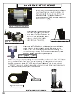
4A. CRADLE STYLE MOUNT

Figure 2 — Cradle style mount pump

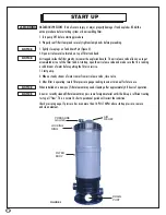
Place tank on top of round opening on base and rotate until the holes in the tank bottom
line up with the holes in the base. Use the remaining mounting bolts from hardware
bag 

(H)

to secure in place. BEFORE bolting down, make sure that the port labeled

“TO PUMP” (open port, without slide valve) is facing the back of the base (longer part of
base indicates back). See Figures 5 and 6 below.

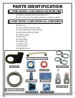
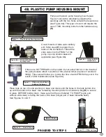
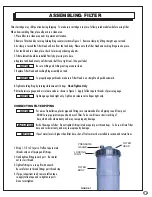
If there are NO THREADS on the inside of your pump inlet or
on the inside of the pump basket, attach slide valve to the
bottom of thru-wall skimmer (in place of standard fitting). This
valve will allow you to stop the flow of water FROM the pool in
the event of filter maintenance (see Figure 4). 

Figure 4 — Slide valve installed in

bottom of skimmer

Figure 5 — Back of base

Figure 6 — Filter on base

PROCEED TO STEP 5

4

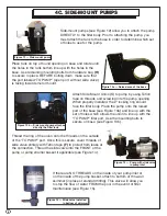
Pumps with cradles located directly under the
motor (see Figure 2) should be aligned with
the holes inside the raised area of the base
(see Figure 3a). This type of mount will
require the use of FOUR mounting bolts from
the hardware bag 

(H)

.

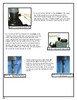
Cover threads of slide valve entirely
with Teflon tape 

(F)

to protect from

leaks at the connection. Thread the
slide valve into the FRONT of the
pump or pump strainer basket if
applicable (see Figure 3b).

Figure 3b — Pump with slide valve

in pump inlet

Back of base

Figure 3a — Raised area on base

Summary of Contents for HYDRO NE635

Page 1: ...PRESSURE CARTRIDGE FILTER INSTRUCTIONS TOOLS REQUIRED 6329 1 Flat Head Screwdriver 2 Pliers NE635 NE636...

Page 2: ...ilter connection hoses C 1 Flex pipe with connection fittings D 4 Stainless steel hose clamps E Pressure gauge F Teflon tape G Straight fitting H Hardware bag I 2 Slide valves J Union adapter K Side M...

Page 3: ...the flow of water to the filter when performing routine maintenance like cleaning your cartridge The location of the second slide valve will vary based on the style of pump you have Directions for the...

Page 4: ...n place of standard fitting This valve will allow you to stop the flow of water FROM the pool in the event of filter maintenance see Figure 4 Figure 4 Slide valve installed in bottom of skimmer Figure...

Page 5: ...n base and rotate until the holes in the tank bottom line up with the holes in the base Use remaining mounting bolts from hardware bag H to secure in place BEFORE bolting down make sure that the port...

Page 6: ...by using Teflon tape on threads and screwing into the pump opening When properly installed the 2 locking ring should face the filter body Place the pump onto the raised part of the base see Figure 13a...

Page 7: ...ump see Figure 18a 18b Cover the threads of that fitting with Teflon tape before screwing it into the opening on the second slide valve Figure 16 Fitting threaded into slide valve Now it s time to att...

Page 8: ...th Teflon tape and thread the union adapter directly into the outlet on the pump At this point you may thread one of the connection fittings directly onto the union adapter and the other onto the FROM...

Page 9: ...Close the valve and the filter is ready to operate Opening for pressure gauge Figure 25a Filter Lid Air relief valve Figure 25b Installing pressure gauge 6 USING SLIDE VALVES Figure 24 Slide valve in...

Page 10: ...stem Hazardous Pressure Incorrectly installed or tested equipment may fail causing severe injury or property damage Read and follow instructions in owner s manual when installing and operating equipme...

Page 11: ...d filter cycle time closely follow disinfectant manufacturer s instructions when cleaning pool or filter Hazardous pressure If filter is improperly disassembled or assembled it will explode under pres...

Page 12: ...for best efficiency use fewest possible fittings Keep piping tight and free of leaks Pump suction line leaks may cause trapped air in filter tank or loss of prime at pump Pump discharge line leaks ma...

Page 13: ...pressure gauge and air release valve as shown in Figure 1 Apply Teflon tape to threads of pressure gauge NOTICE Tighten gauge hand tight only Tighten air release valve finger tight only Filter Cartri...

Page 14: ...release valve and make sure that it is running a solid stream of water before putting the filter in service 1 Start pump 2 When a steady stream of water comes from air release valve close valve 3 Aft...

Page 15: ...SSEMBLY 1 STOP PUMP 2 CLOSE suction and return line valves if used 3 OPEN air release valve on top of filter 4 WAIT until all pressure is released from filter tank and system before loosening either c...

Page 16: ...operating pressure clean filter element NOTICE If filter is used with a spa soak element see Step 2 Special Cleaning Instructions at each regular cleaning With hose wash foreign material from inside...

Page 17: ...hemical feed devices FIGURE 5 FIGURE 6 FIGURE 4 Tank Drain Port NOTICE Some pool disinfectants may clog filter media To maximize media life and filter cycle time closely follow disinfectant manufactur...

Page 18: ...V antifreeze or pipeline Anti Freeze 5 Turn to Page 7 for filter disassembly instructions 6 Remove filter element and store in a warm dry area TROUBLESHOOTING GUIDE 1 Chlorine residual too low maintai...

Page 19: ...is properly sized for your pool 4 Pump too large overpumping reduce flow rate 5 Filter installed backward replumb LONG RECOVERY TIME AFTER HEAVY USAGE 1 Residual Chlorine level is too low add chlorin...

Page 20: ...mps 4 4 4 4 4 4 4 4 4 4 4 4 BS 35858 Teflon Tape 1 1 1 1 1 1 1 1 1 1 1 1 AC 04723 Molded Hoses 1 1 1 1 1 1 1 1 1 1 1 1 BS 39349 Rearmount Gauge 1 1 1 1 1 1 1 1 1 1 1 1 BS 11762 1 4 Air Relief Plug 1 1...

Page 21: ...damage due to misuse This warranty does not cover any damage from the elements such as wind snow heavy rains etc We are not responsible for damage to the cartridge filter due to improper installation...

Reviews: