507270-03B
Page 11 of 58
Issue 1904
Figure 13.
Upflow Applications
Installation Clearances
Top/Plenum
1 in. (25 mm)
*Front
0
Back
0
Sides
0†
Vent
0
Floor
0‡
* Front clearance in alcove installation must be 24 in. (610
mm). Maintain a minimum of 24 in. (610 mm) for front service
access.
† Allow proper clearances to accommodate condensate trap.
‡ For installations on a combustible floor, do not install
the furnace directly on carpeting, tile or other combustible
materials other than wood flooring.
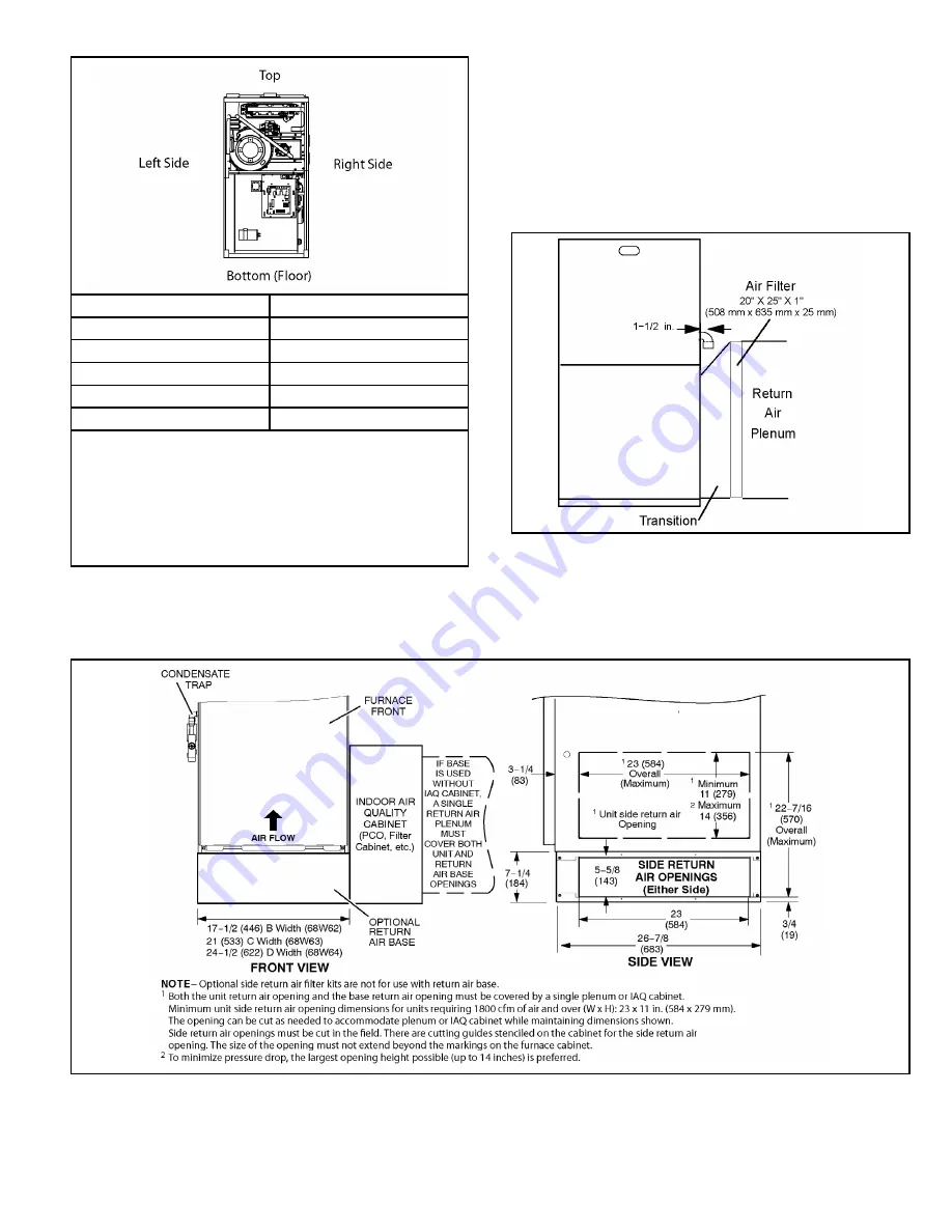
Markings are provided on both sides of the furnace cabinet
for installations that require side return air. Cut the furnace
cabinet at the maximum dimensions shown on Page 2.
Furnace applications which include side return air and a
condensate trap installed on the same side of the cabinet
(trap can be installed remotely within 5 ft.) require either a
return air base or field-fabricated transition to accommodate
an optional IAQ accessory taller than 14.5”. See Figure 14.
Figure 14. Side Return Air
(with Transition and Filter)
Figure 15. Optional Return Air Base
(Upflow Applications Only)
Summary of Contents for BG921UH
Page 3: ...507270 03B Page 3 of 58 Issue 1904 Parts Arrangement Figure 1 ...
Page 24: ...507270 03B Page 24 of 58 Issue 1904 Figure 25 Figure 26 ...
Page 38: ...507270 03B Page 38 of 58 Issue 1904 Figure 58 Trap Drain Assembly Using 1 2 PVC or 3 4 PVC ...
Page 44: ...507270 03B Page 44 of 58 Issue 1904 Figure 67 Typical Wiring Diagram ...


