Specifications are subject to change. See bluesea.com/P12 for current information.
Specifications are subject to change. See bluesea.com/P12 for current information.
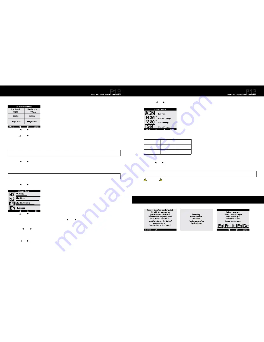
Advanced Charger Setup
1. Press the
Menu
button.
2. Press the
left
or
right
arrow buttons to scroll to the Fan Speed window
3. Press the
Select
button.
4. Press the
up
or
down
arrow buttons to select the desired speed.
a.
High:
The fan will spin up to its maximum speed. This is the recommended setting for optimal performance.
b.
Low:
The fan will spin up to a designated speed (below max). If there is a significant load on the charger, it may limit its maximum output current in
order to maintain a safe internal temperature.
c.
Off:
Forces the Fan to stay off. If there is significant load on the charger, it may limit its maximum output current to maintain a safe internal temperature.
6. Press the
left
or
right
arrow buttons to scroll to the Max Output window.
7. Press the
Select
button
.
8. Press the
up
or
down
arrow buttons to select the desired maximum output amperage. Low output may be selected to reduce load on the AC source.
AC current is approximately 15% of the DC current at 120V line voltage and 7% of the DC current at 240V line voltage.
9. Press the
OK
button
once desired max amperage output is reached.
10. Press the
left
or
right
arrow buttons to scroll to the Display window.
11. Press
the
Select
button
.
NOTE: The designated maximum amperage is the total available amperage to be supplied among all 3 outputs. Selecting an amperage less than the maximum
could result in under charging of batteries.
5. Press the
OK
button once desired speed is reached.
NOTE: Selecting High or Low will not necessarily turn the fan immediately on or increase the fan speed. In either of these settings the charger will only alter the fan
speed if the internal temperature rises enough to warrant fan circulation. The fan Low setting is for quiet mode.
12
12. Press the
up
or
down
arrow buttons to scroll to the desired display setting.
13. Press the
Select
button on the desired display setting to enable editing that setting.
a. Once selected, the amount of contrast and backlight can be adjusted using the
left
and
right
arrow buttons.
b. Press the
OK
button to enable desired setting.
14. Scroll to Backlight Timer and press the
Select
button.
a. Using the
left
and
right
arrow buttons you may adjust the length of seconds the backlight will remain on.
b. The backlight timer can be adjusted between 5 and 59 seconds. It may also be set permanently on or permanently off.
15. Press the
OK
button once desired backlight setting is reached.
16. Scroll to Language and press the
Select
button to adjust the display language.
17. Using the
left
or
right
arrow buttons scroll to the desired language.
18. Press the
OK
button.
Complete this setup to change language, limit fan noise, adjust backlight display and limit AC current draw.
P12
7531 AND 7532 BATTERY CHARGERS
19. Once desired display settings are enabled press
Back
.
20. Press the
left
or
right
arrow button to scroll to the Battery window.
21. Press the
Select
button.
Advanced Charger Setup
(continued)
26. Press the
Back
button twice to return to the Charger Summary screen.
27. Your P12 Battery Charger is now setup and fully operational.
22. While the cursor blinks on battery type press the
Select
button.
23. Use the
left
or
right
arrow buttons to scroll to desired battery type.
24. Press the
OK
button.
25. For optimal charging it is recommended to set absorption timers and End Absorb Amps. If Amp Hour Capacity is known, continue to page 14 for more information.
CAUTION
Selecting a battery type different from the connected batteries could limit the life of the batteries and damage them.
NOTE: to adjust Absorb and Float voltage “User” must be the selected battery type. The default Absorb voltages for each battery type can be seen in
Table E
above.
Warning: Incorrect Absorb and Float voltages could reduce the life of your batteries. Contact your battery manufacturer for recommended Absorb and Float voltages.
13
To reset the P12 Battery Charger to factory defaults, press and hold the two right buttons for ten seconds.
Press the
OK
button for five seconds to proceed with resetting to factory defaults or press the
Cancel
button to return to the previous screen.
Note:
Resetting the P12 Battery Charger to factory defaults will erase previously saved data and settings.
Reset to Manufacturer Defaults
Type
Absorb Volts
Float Volts
FLA – Flooded Lead Acid
14.5V
13.5V
AGM – Absorbed Glass Mat
14.35V
13.3V
Gel – Gelled Electrolyte
14.1V
13.5V
TPPL – Thin Plate Pure Lead
14.7V
13.6V
¹
User Adjustable
12.5V
Default
12.5V
Default
¹
Taken from Odyssey Tech Notes, Northstar operation Manual
Table E:
Default Voltages by Battery Type
Batteries should match in chemistry, although many AGM’s and flooded batteries are
compatible. Based on 25°C (77°F)
P12
7531 AND 7532 BATTERY CHARGERS


