


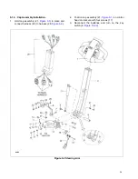


5-1.3. Control Head Removal
1.
Remove the cap assembly as described in para-
graph
2.
Disconnect harness (28,
) from potenti-
) and reversing switch (24).
3.
Remove two screws (11), two lock washers (12)
and two flat washers (13).
WARNING:
When removing the control head in the
following steps, be sure to hold it in place
until the control harness is disconnected.
4.
Remove two screws (5), two washers (6) and two
flat washers (7).
5.
Remove the control head and handle (19).
5-1.4. Control Head Installation
1.
Hold control head and handle (19,
) in
place and install two screws (5), two washers (6)
and two flat washers (7).
2.
Install two screws (11), two lock washers (12) and
two flat washers (13).
3.
Reconnect harness (28,
) to potentiom-
) and reversing switch (24).
4.
Install the cap assembly as described in para-
graph
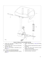
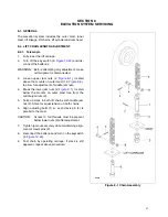
5-1.5. Speed Potentiometer Replacement.
1.
Remove the cap assembly as described in para-
graph
2.
Disconnect harness (28,
) from potenti-
).
3.
Remove screw (4), washer (3) and control knob
(2) from potentiometer (15).
4.
Remove screw (4), washer (3) and control knob
(14) from other side of potentiometer (15).
5.
Remove screw (1), lock washer (6) and flat
washer (7).
6.
Remove screw (16), lock washer (6) and flat
washer (7) and remove potentiometer (15) from
bracket (20).
7.
Position new potentiometer (15) in bracket (20)
and secure with screw (16), lock washer (6) and
flat washer (7).
8.
Install screw (1), lock washer (6) and flat washer
(7).
9.
Install control knob (14) on potentiometer (15) and
secure with screw (4), and washer (3).
10. Install control knob (2) on the other side of poten-
tiometer (15) and secure with screw (4), and
washer (3).
11. Connect harness (28,
) to potentiome-
ter (15,
).
12. Install the cap assembly as described in para-
graph
5-1.6. Belly-Button Switch Replacement.
1.
Remove the cap assembly as described in para-
graph
2.
Disconnect harness (28,
) from revers-
ing switch (25,
).
3.
Remove screw (1), lock washer (6) and flat
washer (7).
4.
Remove screw (16), lock washer (6) and flat
washer (7) and remove switch assembly (24) from
bracket (20).
5.
Remove pin (5,
), bracket (4), and
spring (2) from button (1).
6.
Remove two pins (3) and switch assembly (25,
) from bracket (4,
7.
Position the new switch assembly (25,
)
in bracket (4,
) and secure with two pins
(3).
8.
Position bracket (4) in button (1) and install pin
(5).
9.
Position switch assembly (24,
) on
bracket (10) and secure with two screws (13).
10. Reconnect harness (28,
) to reversing
switch (25,
).
11. Install the cap assembly as described in para-
graph
5-1.7. Horn Switch Replacement.
1.
Remove the cap assembly as described in para-
graph
2.
Remove three screws (11,
), bracket
(14) and springs (13).
3.
Remove two pins (12) and defective switch from
bracket (14).
4.
Unsolder harness from defective switch and con-
nect it to the new switch.
37
Summary of Contents for BGL-22
Page 12: ...NOTES 12...
Page 18: ...NOTES 18...
Page 34: ...NOTES 34...
Page 39: ...Figure 5 4 Cap Assembly R6878 39...
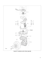
Page 42: ...Figure 6 1 Transmission Motor Brake Assembly R6879 42...
Page 44: ...Figure 7 1 Transmission Motor Brake Assembly R6879 44...
Page 45: ...Figure 7 2 Load Wheels R6882 45...
Page 46: ...NOTES 46...
Page 48: ...Figure 8 2 Elevation System Telescopic R6883 48...
Page 50: ...Figure 8 3 Mast TRIMAST R6884 50...
Page 52: ...NOTES 52...
Page 54: ...Figure 9 1 Hydraulic System R6886 54...
Page 56: ...Figure 9 3 Hydraulic System TRIMAST R6888 56...
Page 58: ...Figure 9 4 Elevation System Telescopic R6883 58...
Page 59: ...Figure 9 5 Lift Cylinder Telescopic R6889 59...
Page 61: ...Figure 9 6 Elevation System TRIMAST R6884 61...
Page 62: ...Figure 9 7 Free Lift Cylinder TRIMAST R6890 62...
Page 64: ...Figure 9 8 Secondary Lift Cylinder TRIMAST R6891 64...
Page 67: ...Figure 9 10 Tilt Cylinder R6893 67...
Page 68: ...NOTES 68...
Page 70: ...Figure 10 1 Electrical System R6478 R6894 70...
Page 71: ...Figure 10 2 Electrical Panel R6478 R6895 71...
Page 73: ...Figure 10 3 Transmission Motor Brake Assembly R6879 73...
Page 74: ...NOTES 74...
Page 75: ...SECTION 11 OPTIONAL EQUIPMENT 75...
Page 76: ...NOTES 76...
Page 78: ...Figure 12 1 Steering System R6876 78...
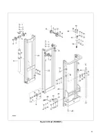
Page 80: ...Figure 12 2 Control Head R6877 80...
Page 82: ...Figure 12 3 Cap Assembly R6878 82...
Page 85: ...NOTES 85...
Page 86: ...Figure 12 5 Transmission Motor Brake Assembly R6879 86...
Page 89: ...NOTES 89...
Page 90: ...Figure 12 7 Frame R6881 90...
Page 92: ...Figure 12 8 Load Wheels R6882 92...
Page 94: ...Figure 12 9 Elevation System Telescopic R6883 94...
Page 96: ...Figure 12 10 Elevation System TRIMAST R6884 96...
Page 98: ...Figure 12 11 Lift Carriage R6815 98...
Page 101: ...NOTES 101...
Page 102: ...Figure 12 13 Hydraulic System R6665 102...
Page 104: ...Figure 12 14 Pump Motor R6886 104...
Page 107: ...NOTES 107...
Page 108: ...Figure 12 16 Hydraulic System TRIMAST R6888 108...
Page 110: ...Figure 12 17 Tilt Cylinder Mounting R6892 110...
Page 112: ...Figure 12 18 Lift Cylinder Telescopic R6889 112...
Page 114: ...Figure 12 19 Free Lift Cylinder TRIMAST R6890 114...
Page 116: ...Figure 12 20 Secondary Lift Cylinder TRIMAST R6891 116...
Page 118: ...Figure 12 21 Tilt Cylinder R6893 118...
Page 120: ...Figure 12 22 Electrical System R6894 120...
Page 123: ...NOTES 123...
Page 124: ...Figure 12 24 Drive Motor R6630 124...
Page 128: ...NOTES 128...
Page 129: ...129...