


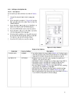
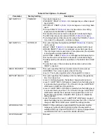
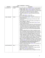


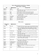


Table 4-2 Set Options - Continued
Parameter
Factory Setting
Description
AUX OUTPUT #1
BRAKE
This option handles output CNA#3 (
). It can be used as:
• BRAKE: CNA#3 (
) drives an electromechanical Brake.
• HYDROCOMNT: CNA#3 (
) drives the contractor for a
hydraulic steering function when the direction input or brake pedal
input are active or a movement of the truck is detected.
• EX.HYDRO: CNA#3 (
) drives the contractor for a
hydraulic steering function when the exclusive hydro input is
active.
• FREE: CNA#3 (
) is not used.
The current this output can sink is up to 3Adc.
PEDAL BRAKING
NONE
The analog input CNA#18 (
) has one of two functions:
• Pedal Braking input.
• Command input for lifting/lowering proportional valves in MDI-
PRC version.
To turn from the first to the second function is just enough to set
PEDAL BRAKING to HNONE.
This option handles the analog input CNA#18 (
) when
used as pedal braking input:
• ANALOG: With this setting it is possible to modulate the strength
of the braking when the accelerator is released. The strength of
the braking is proportional to the brake pedal potentiometer con-
nected to this input. When the pedal potentiometer voltage is
equal/less than the SET POT BRK MIN, the minimum release
braking strength is applied (following the RELEASE BRAKING
setting).
When the pedal potentiometer voltage is equal/higher than the
SET POT BRK MAX, the maximum release braking strength is
applied (following the PEDAL BRAKING setting). In the intermedi-
ate position, the electrical braking strength is a linear function
between the minimum (RELEASED BRAKING) and maximum
(PEDAL BRAKING) intensity. When there is also a switch con-
nected to the pedal braking (i.e. SET INPUT #4 to level BRAKE), it
must be closed, otherwise the release braking is stuck to the mini-
mum strength disregarding the pedal potentiometer position.
• DIGITAL: No pedal potentiometer is expected. Only when both the
SET INPUT #4 is Level BRAKE and the brake switch connected to
CNB#4 (
) is closed, the release electrical braking follows
the PEDAL BRAKING setting (maximum strength); in all of the
other conditions the release electrical braking follows the
RELEASE BRAKING setting (minimum strength).
• NONE: The analog input CNA#18 (
) is not used for the
release braking modulation.
QUICK INVERSION
BELLY
This option specifies the quick inversion mode when the SET
INPUT #4 is set BELLY. It can be set as:
• NONE: The quick inversion function is not managed (no effect
when CNB#7 (
) switches over).
• TIMED: The quick inversion function is timed.
• BELLY: The quick inversion function is managed but not timed.
25
Summary of Contents for BGL-22
Page 12: ...NOTES 12...
Page 18: ...NOTES 18...
Page 34: ...NOTES 34...
Page 39: ...Figure 5 4 Cap Assembly R6878 39...
Page 42: ...Figure 6 1 Transmission Motor Brake Assembly R6879 42...
Page 44: ...Figure 7 1 Transmission Motor Brake Assembly R6879 44...
Page 45: ...Figure 7 2 Load Wheels R6882 45...
Page 46: ...NOTES 46...
Page 48: ...Figure 8 2 Elevation System Telescopic R6883 48...
Page 50: ...Figure 8 3 Mast TRIMAST R6884 50...
Page 52: ...NOTES 52...
Page 54: ...Figure 9 1 Hydraulic System R6886 54...
Page 56: ...Figure 9 3 Hydraulic System TRIMAST R6888 56...
Page 58: ...Figure 9 4 Elevation System Telescopic R6883 58...
Page 59: ...Figure 9 5 Lift Cylinder Telescopic R6889 59...
Page 61: ...Figure 9 6 Elevation System TRIMAST R6884 61...
Page 62: ...Figure 9 7 Free Lift Cylinder TRIMAST R6890 62...
Page 64: ...Figure 9 8 Secondary Lift Cylinder TRIMAST R6891 64...
Page 67: ...Figure 9 10 Tilt Cylinder R6893 67...
Page 68: ...NOTES 68...
Page 70: ...Figure 10 1 Electrical System R6478 R6894 70...
Page 71: ...Figure 10 2 Electrical Panel R6478 R6895 71...
Page 73: ...Figure 10 3 Transmission Motor Brake Assembly R6879 73...
Page 74: ...NOTES 74...
Page 75: ...SECTION 11 OPTIONAL EQUIPMENT 75...
Page 76: ...NOTES 76...
Page 78: ...Figure 12 1 Steering System R6876 78...
Page 80: ...Figure 12 2 Control Head R6877 80...
Page 82: ...Figure 12 3 Cap Assembly R6878 82...
Page 85: ...NOTES 85...
Page 86: ...Figure 12 5 Transmission Motor Brake Assembly R6879 86...
Page 89: ...NOTES 89...
Page 90: ...Figure 12 7 Frame R6881 90...
Page 92: ...Figure 12 8 Load Wheels R6882 92...
Page 94: ...Figure 12 9 Elevation System Telescopic R6883 94...
Page 96: ...Figure 12 10 Elevation System TRIMAST R6884 96...
Page 98: ...Figure 12 11 Lift Carriage R6815 98...
Page 101: ...NOTES 101...
Page 102: ...Figure 12 13 Hydraulic System R6665 102...
Page 104: ...Figure 12 14 Pump Motor R6886 104...
Page 107: ...NOTES 107...
Page 108: ...Figure 12 16 Hydraulic System TRIMAST R6888 108...
Page 110: ...Figure 12 17 Tilt Cylinder Mounting R6892 110...
Page 112: ...Figure 12 18 Lift Cylinder Telescopic R6889 112...
Page 114: ...Figure 12 19 Free Lift Cylinder TRIMAST R6890 114...
Page 116: ...Figure 12 20 Secondary Lift Cylinder TRIMAST R6891 116...
Page 118: ...Figure 12 21 Tilt Cylinder R6893 118...
Page 120: ...Figure 12 22 Electrical System R6894 120...
Page 123: ...NOTES 123...
Page 124: ...Figure 12 24 Drive Motor R6630 124...
Page 128: ...NOTES 128...
Page 129: ...129...