BLUE EMBER GRILLS FG50069 Assembly Manual And Use And Care Download Page 17

17

IMPORTANT SAFEGUARDS

READ AND FOLLOW ALL SAFETY INSTRUCTIONS

Read and follow all instructions that are on the product or provided with product.

The following basic safety precautions apply when using electrical appliances:

•  Read all instructions.
• Do not touch surfaces that may be hot. Use handles or knobs provided.
• To protect against electrical shock do not immerse cord, plugs, portable appliances (or other specific part or parts)in water or other liquid.
• Close supervision is necessary when any appliance is used by or near children.

(i) Portable - Remove plug from outlet when the appliance is not in use, before putting on or taking off parts, and before cleaning.  Allow to cool
before handling.
(ii) Permanently installed - Make sure appliance is OFF when not in use, before putting on or taking off parts, and before cleaning.

•  Portable - Do not operate any appliance with a damaged cord or plug or after the appliance malfunctions or is dropped or damaged in any manner.

Return appliance to the nearest authorized service facility for examination, repair, or electrical or mechanical adjustment.

•  The use of accessory attachments not recommended by the appliance manufacturer may cause injuries.
•  Do not let cord hang over edge of table or counter or touch hot surfaces.
•  Do not place on or near a hot gas or electric burner or in a heated oven.
•  Extreme caution must be used when moving an appliance containing hot oil or other hot liquids.
•  Where applicable, always attach plug to appliance and check that the control is OFF before plugging cord into wall outlet. To disconnect, turn the

control to OFF, then remove plug from wall outlet.

•  Do not use appliance for other than intended use.
•  Avoid contacting moving parts.
•  Save these instructions.
•  Never remove the grounding plug or use with an adapter of 2 prongs; and
•  Use only extension cords with a 3 prong grounding plug, rated for the power of the equipment, and approved for outdoor use with a W-A marking.
•  When connecting, first connect plug to the outdoor cooking gas appliance then plug appliance into the outlet.
•  Use only a Ground Fault Interrupter (GFI) protected circuit with this outdoor cooking gas appliance.
•  Do not use an extension cord.
•  Do not install or use within 10 feet of a pool.
•  WARNING: Risk of Electric Shock.  When used outdoors, install only to a Class A GFCI protected receptacle that is weatherproof with the power unit

connected to the receptacle.  If one is not provided, contact a qualified electrician for proper installation.  Ensure that the power unit and cord do not
interfere with completely closing the receptacle cover.

•  WARNING: Risk of Electric Shock.  Install only to a covered Class A GFCI receptacle that has an enclosure that is weatherproof with the attachment

plug cap inserted or removed.

SAVE THESE INSTRUCTIONS

- This manual contains important safety and operating instruction for power units.

ADDITIONAL IMPORTANT SAFETY PRECAUTIONS

•  Read all instructions before using your rotisserie.
•  This rotisserie is for outdoor use only.
•  Remove motor and store in a dry place when not in use.
•  Do not touch hot surfaces. Use barbecue mitts.
•  This rotisserie is not for use by children.
•  To protect against electrical hazards do not immerse cord, plugs, or motor in water or other liquids.
•  Unplug the motor from outlet when not in use or before cleaning.
•  If the rotisserie motors should malfunction, stop operating with it and replace with a new rotisserie motor.
•  The rotisserie motor is equipped with a three prong (grounding) power cord for your protection against shock hazard.
•  The power cord should be plugged directly into a properly grounded three prong receptacle. If use of an extension cord is required, be sure that it is

a minimum 16 AWG(1.3mm), 3-wire, well insulated cord marked for OUTDOOR USE ONLY and properly grounded.

•  When using an extension cord, make sure it is not in contact with a hot or sharp surface.
•  Outdoor extension cords should be marked with the letters “W-A” and a tag stating “Suitable for use with outdoor appliances”.
•  Do not let cord hang over any sharp edge or hot surface.
•  To reduce the risk of electric shock, keep extension cord connection dry and off the ground.
•  A short power cord is supplied to reduce the risk of tripping over the cord. Extension cords may be used, but caution must be taken to prevent

tripping over the cord.

•  In absence of local codes the rotisserie motor must be grounded electrically in accordance with the National Electric Code, ANSI / NFPA 70, or

Canadian Electrical Code, CSA C22.1.

• Ensure all packaging materials including foam, cardboard, advertising artwork, plastic bags, or other flammable materials have been removed from

the BBQ/grill prior to use for the first time.
Warning:  Do not remove any warning or instructional stickers/tags that are adhered to the BBQ/grill.  These warning/instructional stickers/tags are
intended for the user safety and should be read and fully understood before and during use of the BBQ/grill.  Removing items such as
warning/instructional stickers/tags will invalidate warranty.

• Clean grease cup before each use
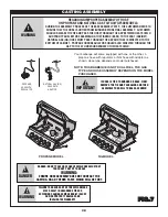
• Before using for the first time and after transporting or moving the bbq/grill, ensure that the burner tubes are fully inserted into the valves

Summary of Contents for FG50069

Page 1: ...sion may result if these instructions are ignored It is your responsibility to see that your new barbeque is assembled installed maintained and cared for properly Failing to carefully follow the instr...

Page 2: ...REMOVED FROM THE PICTURE OR HIDDEN TO BETTER ILLUSTRATE AND SIMPLIFY THE DIRECTIONS THESE INSTALLATION STEPS APPLY TO ALL MODELS LISTED UNLESS OTHERWISE SPECIFIED Getting Familiar With Your Barbeque...

Page 3: ...ULTING IN PROPERTY DAMAGE PERSONAL INJURY OR DEATH GETTING FAMILIAR WITH YOUR BARBEQUE Liquid propane gas is not natural gas The conversion or attempted use of natural gas in a liquid propane unit or...

Page 4: ...SHOWN WARNING DO NOT USE THIS GAS OUTDOOR APPLIANCE UNDER ANY OVERHEAD COMBUSTIBLE CONSTRUCTION WHEN DECIDING WHERE TO PLACE YOUR APPLIANCE FOLLOW THESE MINIMUM CLEARANCE DISTANCES TO ADJACENT COMBUST...

Page 5: ...P O L fitting by use of adapters or any other means could result in damage fire or injury and may negate the important safety features designed TM FILLING STOPS AT 80 NEW OPD HANDWHEEL Fig 3 O P D FL...

Page 6: ...s hot Never store or transport the LP cylinder where temperatures can reach 125 F Do not leave an LP cylinder in a car on a hot day Do not use a damaged LP cylinder Dented or rusty LP cylinders or LP...

Page 7: ...AND TIGHTEN ONLY WARNING WARNING INDICATES AN POTENTIALLY HAZARDOUS SITUATION WHICH IF NOT AVOIDED COULD RESULT IN DEATH OR SERIOUS INJURY Fig 5 Fig 6 REGULATOR REGULATOR STRAIGHT Q C C I Q C C I Shou...

Page 8: ...pressure in excess of 3 5 kPa 1 2 p s i The appliance must be isolated from the gas supply piping system by closing its individual manual shut off valve during any pressure testing of the gas supply...

Page 9: ...ollowing steps 1 disconnect the side burner hose and sonarque wiring if your model comes equipped with either of these features 2 remove the wing nuts from the side shelves and completely remove the s...

Page 10: ...ease pan in place The grease pan has unique tabs that lock and secure the grease pan in place 3 install the grease pan by sliding it into place using the rails as a guide Figure 8A CORRECT INSTALLATIO...

Page 11: ...y water and wipe dry Do not use citrisol abrasive cleaners degreasers or a concentrated grill cleaner on plastic parts Damage to and failure of parts can result CASTING INTERIOR AND WARMING RACK At le...

Page 12: ...tional side burner and rotisserie burners the right small knob operates the side burner and the small left knob operates the rotisserie Figure 9A IGNITOR BATTERY Ensure AA BATTERY is installed correct...

Page 13: ...wait 5 minutes to clear the gas 8 Repeat steps 1 to 7 If burner still fails to light refer to Troubleshooting Guide to determine cause and solution or try the Match Lighting procedure Fig 11B CAUTION...

Page 14: ...ting device to activate If the leak test is negative then carefully follow the lighting procedures step by step ensuring all valves including tank are off before starting 1 2 Fig 12B SIDE BURNER OPTIO...

Page 15: ...5 If burner does not light immediately within five seconds turn the burner control knob OFF and wait 5 minutes to clear the gas 6 Repeat steps 1 to 5 If burner still fails to light refer to the Troubl...

Page 16: ...hen raise the lid and continue to operate your barbeque on HIGH for an additional 5 minutes Your barbeque is now ready for cooking Note Break in procedure is not required for Side Burner or Rotisserie...

Page 17: ...the power unit and cord do not interfere with completely closing the receptacle cover WARNING Risk of Electric Shock Install only to a covered Class A GFCI receptacle that has an enclosure that is we...

Page 18: ...nce halfway through the grilling process Other good candidates for this cooking method are thin cuts of meat sausages vegetables kabobs and fillets For Direct Cooking Preheat grill by setting all burn...

Page 19: ...s desirable to create the smoke which gives barbequed food its unique flavor and appearance However excessive flare up can not only ruin your food it may lead to a dangerous condition as well By exces...

Page 20: ...nder Follow correct lighting procedure Page 13 to 15 Perform leak test and correct leaks Page 9 Tighten regulator fully hand tight into cylinder Page 7 Check battery orientation Has battery been used...

Page 21: ...her I e hail hurricanes earthquake tornados 13 Surface rust or discoloration of stainless steel 14 Discoloration or paint chipping surface rust or rust perforation due to paint chipping resulting from...

Page 22: ...rill parts shown in the assembly steps may differ slightly in appearance from those on your particular grill model However the method of assembly remains the same SP46 21 4 1 4 B HEX HEAD SELF TAPPING...

Page 23: ...CASTER ASSEMBLY Attach casters to bottom of base as shown FIG 2 Assembled View 23...

Page 24: ...t corner for bottle opener Attach bottle opener to right panel as shown FIG 3 Right hand Panel Assembled View SP84 18 8 1 4 20 X 5 HEX HD BOLT SP84 18 8 1 4 20 X 5 HEX HD BOLT SP53 16 2 1 4 20 NUT HEX...

Page 25: ...BOLT TRANSFORMER BOX SP54 21 2 10 24 SCREW SP43 16 2 10 24 NUT Attach rear panel by sliding notches over screws on side panels as shown Tighten screws Install Electrical box with Screws and Nuts as s...

Page 26: ...tach heat shield as shown Tighten screws FIG 5 Assembled View SP83 18 4 1 4 20 X 50 CARRIAGE BOLT SP83 18 4 1 4 20X 50 CARRIAGE BOLT SP53 16 4 1 4 20 NUT HEX HD FLANGED SP53 16 4 1 4 20 NUT HEX HD FLA...

Page 27: ...oors into upper holes as shown A Drop locking pins through lower holes in door into base assembly B Once in position rotate pins into locked position as shown FIG 6 Assembled View A B Locked position...

Page 28: ...ANGER DO NOT PASS HOSE ABOVE SHIELD HOSE MUST NOT TOUCH ANY PART OF THE BASE WARNING ENSURE HOSE ASSEMBLY DOES NOT CONTACT THE CASTING OR ANY OTHER PARTS WHICH WILL GET HOT WARNING FAILURE TO ENSURE A...

Page 29: ...3 16 4 1 4 20 NUT HEX HD FLANGED IMPORTANT IF HOSE IS TIED TO BURNER OR BASE FIRST REMOVE THE TIE AND PACKAGING AND THEN ASSEMBLE THE GRILL TO BASE AS SHOWN WARNING DO NOT PASS HOSE BEHIND THE HEAT SH...

Page 30: ...DS TO ENSURE THAT THE HOSE IS UNTIED FROM BURNER BEFORE FINAL ASSEMBLY CUSTOMER SHOULD RELEASE THE TIE AND PASS THE HOSE THROUGH THE GAP BETWEEN HEAT SHIELD AND FRONT PANEL BEFORE ASSEMBLING THE FIREB...

Page 31: ...ting as shown Step 2 Install 3 grids as shown Step 3 Install warming rack into supports as shown Step 4 Install AA BATTERY into ignitor put negative side of battery in rst Step 3 Step 2 Step 1 BATTERY...

Page 32: ...nd drop into locking position B Insert wingbolt into middle hole in bracket to lock shelf in position C Position ice wine bucket and condiment tray as shown Insert side burner grill Assembled View FIG...

Page 33: ...tioned in tube end Attach side burner Ignitor wire to terminal on side burner bracket Ensure you read and understand warning below before proceeding FIG 11 A B Grooves Ignitor Wire Electrode WARNING C...

Page 34: ...H USE TO PREVENT GREASE BUILDUP AND OVERFLOW FAILURE TO DO SO MAY RESULT IN A GREASE FIRE MAKE SURE THE BBQ GRILL IS COOL BEFORE REMOVING THE GREASE PAN Step 1 Look at the back of your grill With the...

Page 35: ...ring it INCORRECT INSTALLATION This picture shows a Grease Pan that is not properly installed If the grease pan is not fully inserted and locked in place the edge of the grease pan will extend more th...

Page 36: ...m 16 AWG 3 wire well insulated cord marked for OUTDOOR USE ONLY and properly grounded CAUTION To ensure continued protection against risk of electric shock connect to properly earthed outlets only Tra...

Page 37: ...nt For NG models direct the hose through the hole in the base as shown FOR PROPANE MODELS PLEASE FOLLOW THE FOLLOWING STEPS DANGER DANGER HOSE MUST NOT TOUCH ANY PART OF THE BASE WARNING ENSURE HOSE A...

Page 38: ...Before proceeding with the following steps ensure you have read L P Gas Cylinder Hose and Regulator Sections of the USE AND CARE INSTRUCTIONS located at the front of this manual The L P gas cylinder...

Page 39: ...P93 5 TUBE BURNER AIR SHUTTER 2 27 3 SP60 20 IGNITER ASSEMBLY MAIN BURNER SECTION 03 CART ASSEMBLY 3 01 1 SP160 9 500 BACK PAN PLAIN 3 02 1 SP107 9 500 GRILL PANEL FRONT 3 03 1 SP165A 42 500 UNIVERSAL...

Page 40: ...DEL 6 10 1 SP50 6 BOTTLE OPENER 6 11 1 SP164A 3 CAST IRON COOK GRATE FG MODELS X COLOR B Black C Charcoal BL Blue E Metallic Silver Gas Barbeque Grill Model FG50069 HOW TO ORDER SPARE PARTS When order...

Page 41: ...ZKLFK ZLOO JHW KRW T 7 26 5 8 725 0867 167 7 7 5217 2 7 57 6 6 2 1 1 7 6 16758 7 216 T 1 9 5 23 5 7 7 287 3523 5 167 5 6 3 1 66 0 T The grease pan and grease tray should be checked cleaned and replac...

Reviews: