background image

CPU—input of the keypad


29 

Summary of Contents for VIVO ONE

Page 1: ...BLU Model VIVO ONE VIVO ONE SERVICE MANUAL ASSEMBLY DISASSEMBLY 1 ...

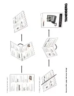
Page 2: ...Chapter 1 EXPLODED VIEW AND COMPONENT DISPOSAL EXPLODED DIAGRAM 2 ...

Page 3: ...BLU Model VIVO ONE Disassembly 1 Use SIM Tray Eject tool to separate Device and SIM tray and Remove 2 pcs pentagon screws by screw driver 2 Remove battery cover 3 ...

Page 4: ...ONE 3 Remove 13 pcs screws by screw driver screw drive torque 0 6kgf cm 4 Separate rear housing from handset by black stick 5 Separate PCB connector with LCM FPC Battery FPC Side Key FPC fingerprint FPC front camera 4 ...

Page 5: ...BLU Model VIVO ONE 6 Remove PCBA screw separate motor and antenna cable connector back camera 7 Separate Side Key FPC and Receiver light sensation rubber in accordance with the direction of the arrow 5 ...

Page 6: ...BLU Model VIVO ONE 8 Remove the Speaker module FPC and Antenna Board Speaker module sub board from tweezers 9 Separate battery and LCM FPC 10 All components 6 ...

Page 7: ...l VIVO ONE Assembly 1 Apply the UV on front housing by UV machine Combine front housing and LCM with glue 7 2 Insatll the maintenance jig and Maintain pressure with 45minsTake apart jigs after the time is over ...

Page 8: ...BLU Model VIVO ONE 3 Install REC and F Camera Foam breathe led guide sensor rubber 4 Install the F Camera B Camera CONN 5 Install the motor RF cable side key FPC 8 ...

Page 9: ...BLU Model VIVO ONE 6 Fasten the Screw to fix the MB 7 Paste side key FPC and waterproof label 9 8 Assemble SPK and SUB ...

Page 10: ...U Model VIVO ONE 9 Paste conductive tape and waterproof label 10 Paste SPK mylar and route the cable and connect conn in the SB 11 Assemble BATTERY Connector on PCB Main and stick Battery on Bezel case 10 ...

Page 11: ...BLU Model VIVO ONE 12 Process COMBO_ANTENNA_FRAME_ASM 13 Assemble ANTENNA FRAME ASM 14 Fasten the 13 pcs screw to combine the B housing 11 ...

Page 12: ...BLU Model VIVO ONE 15 Paste POAM 16 Paste battery waterproof label and screw seal label 17 Paste fingerprint and assembly battery cover 12 ...

Page 13: ...BLU Model VIVO ONE 18 Insert METAL SIMTRAY to Device and Fasten the 2 pcs pentagon screw to combine the battery cover 13 ...

Page 14: ...DISASSEMBLY AND ASSEMBLY SERVICE TOOLS 14 ...

Page 15: ...Solder wire soldering paste Wrist grounding strap Antistatic gloves Metal tweezers Screw driver SRT 6 Plates 15 ...

Page 16: ...Chapter 2 SYSTEM BLOCK DIAGRAM 16 ...

Page 17: ...Chapter 3 INSTRUCTION OF THE UNIT CIRCUIT Circuit instruction of CPU 22 ...

Page 18: ...23 ...

Page 19: ...24 ...

Page 20: ...25 ...

Page 21: ...26 ...

Page 22: ...27 ...

Page 23: ...28 ...

Page 24: ...CPU input of the keypad 29 ...

Page 25: ...The circuit of SIM1 SIM2 T FLASH 30 ...

Page 26: ...EMMC MCP 31 ...

Page 27: ...Bluetooth WIFI GPS FM 32 ...

Page 28: ...Power supply port 33 ...

Page 29: ...29 ...

Page 30: ...30 ...

Page 31: ...31 ...

Page 32: ...Battery connector 37 ...

Page 33: ...Charger Circuit 38 ...

Page 34: ...I O connector 39 ...

Page 35: ...40 RF TX RX ...

Page 36: ...41 ...

Page 37: ...42 ...

Page 38: ...43 REC MIC ...

Page 39: ...44 HEADSET REC MIC ...

Page 40: ...LCD POWER LCD BACKLIGHT 45 ...

Page 41: ...Rear Camera Connector 46 ...

Page 42: ...47 Front Camera Connector ...

Page 43: ...48 Flash LED ...

Page 44: ...49 ALPS G SENSOR ...

Page 45: ...50 Finger print ...

Page 46: ...Chapter4 PCB Layout chart PCB layout SIDE A 51 ...

Page 47: ...PCB layout SIDE B 52 ...

Page 48: ...53 ...

Page 49: ...or replace SIM socket NO End OK Check if SIM card Is invalid Yes Replace SIM card Connect to the voltage regulator and check if the current is OK Power may be damaged Test if the voltage PIN of SIM card isn t 2 8V and if the third forth fifth pins have pulse voltage YES MT6739 may have fault YES NO NO NO Replace MT6739 YES ...

Page 50: ...ector NO End OK Connect to the voltage regulator and verify it can be power on Yes Replace battery Check if the current is powering 30 40mA Update software to the latest version YES MT6357 may have fault YES NO NO NO Resolder or replace MT6357 Test flowchart of can not power on main NO ...

Page 51: ... damaged NO Replace or clean speaker YES Check if headphone is connect OK Yes Replace headphone Remove headphone and test it by millimeter to check if the connection is ok Replace headphone NO Check if there is audio signal from MT6357 YES NO YES NO Replace MT6357 The test flowchart of head phone ...

Page 52: ... broken Replace LCD YES Check if LCD interface connects OK Replace LCD FPC END OK Check if enable signals and MIPI signals are normal or not NO YES NO Replace or resolder MT6739 Test flowchart of no display or display abnormally Clean and resolder LCD connector NO NO ...

Page 53: ...ck if USB interface connects OK Connect USB cable and check current is correct Disconnect cable immediately and touch chip gently to check if chip is hot YES Check VCORE VDD VADO VTCXO VRTC VMEM and clock signal of 26Mhz 32khz YES NO NO Replace or Resolder MT6357 Clean and resolder LCD connector NO NO OK Replace or resolder USB connector YES ...

Reviews: