background image

Blodgett is proud to support the Commercial Food Equipment
Service Association (CFESA). We recognize and applaud
CFESA's ongoing efforts to improve the quality of technical
service in the industry.

WARNING

Improper installation, adjustment, alteration, service or maintenance

can cause property damage, injury or death. Read the installation,

operating and maintenance instructions thoroughly before

installing or servicing this equipment.

NOTICE

During the warranty period, ALL parts replacement and servicing should be performed by

your Blodgett Authorized Service Agent.  Service that is performed by parties other than

your Blodgett Authorized Service Agent may void your warranty.

NOTICE

Using any parts other than genuine Blodgett factory manufactured parts relieves the manu-

facturer of all warranty and liability.

NOTICE

Blodgett reserves the right to change specifications at any time.

G.S. Blodgett Corporation • 50 Lakeside Avenue, Box 586 • Burlington, Vermont 05402 • USA

Telephone (800) 331-5842, (802) 860-3700 • Fax: (802) 864-0183

www.blodgettcorp.com

Summary of Contents for BG2136 Double

Page 1: ......

Page 2: ...er flammable vapors or liquids in the vicinity of this or any other appliance The information contained in this manual is important for the proper installation use and maintenance of this oven Adherence to these proceduresandinstructionswillresultinsatisfactorybakingresults and long trouble free service Please read thismanual carefully and retain it for future reference Errors Descriptive typograp...

Page 3: ...kinds of ovens for every foodservice operation regardless of size application orbudget Infact nooneoffersmoremodels sizes andovenapplicationsthan Blodgett gas and electric full size half size countertop and deck con vection Cook n Hold Combi Ovens and the industry s highest quality Pizza Oven line For more information on the full line of Blodgett ovens contact your Blodgettrepresentative ...

Page 4: ...iv ...

Page 5: ...or Installation 11 E Final Assembly 12 IV ELECTRICAL SUPPLY 13 A Additional Information Gas Ovens 13 B Connection 13 V GAS SUPPLY 14 A Gas Utility Rough In Recommendations 14 B Gas Conversion 14 C Connection 14 TABLEOFCONTENTS Continued Page SECTION 3 OPERATION 16 I LOCATION AND DESCRIPTION OF CONTROLS 16 A BLOWER Switch 16 B CONVEYOR Switch 16 C Conveyor Speed Controller 16 D Digital Temperature ...

Page 6: ...vi NOTES ...

Page 7: ...r C Eyebrows Can be adjusted to various heights to prevent heat loss into the environment D End Plugs Allow access to the oven s interior E Control Panel Location of the operating controls for the oven Refer to Section 3 Operation for details F Machinery Compartment and Control Compartment Doors Allow access to the oven s interior components One door is located at each end of the oven No user serv...

Page 8: ...ice Rated Gas Orifice DK FI NL DE BE FR FI DE NL ES UK Manifold Heat Type dia I2H I2L I2E I2E I3B P I3 Pressure Input G20 2 3749 20 20 20 11 21 22 36 mm mbar mbar mbar mbar kW hr G25 2 3749 25 16 19 22 36 mm mbar mbar kW hr G30 1 3970 29 or 50 28 30 37 26 2 22 59 mm mbar or 50 mbar mbar kW hr Table 1 4 Gas orifice and pressure specifications per oven cavity Domestic and standard export ovens Orifi...

Page 9: ... installation must conform with local codes In the absence of local codes gas oven installations must conform with the Natural Gas Installation Code CAN CGA B149 1 or the Propane Gas Installation Code CAN CGA B149 2 as applicable Installed ovens must be electrically grounded in accordance with local codes or in the absence of local codes with the Canadian Electrical Code CSA C22 2 NOTE In the USA ...

Page 10: ...king casters Item 6 CE approved ovens include 4 non braking casters Item 6 SOLELY for the purpose of moving the oven to the installation location Casters are NOT suitable for use as part of CE oven installations Refer to the notice on the preceding page 7 4 4 4 22450 0028 No Yes Leg adjustable 6 152mm 8 1 1 1 21392 0004 Yes No Eyebolt 3 4 9 A R A R A R 220373 Yes Yes Hex bolt 3 8 16 x 1 NOTE CE ap...

Page 11: ...ARANCES Rear of Oven to Wall 6 150mm Non control End of Oven to Wall 0 Control End of Oven to Wall 0 1 2 3 2 3 3 3 1 Figure2 3 MODELBG2136DOUBLEOVENDIMENSIONS 2 3 3 3 1 GASINLET ELECTRICALJUNCTIONBOX RECOMMENDEDMINIMUMCLEARANCES Rear of Oven to Wall 6 150mm Non control End of Oven to Wall 0 Control End of Oven to Wall 0 1 2 3 ...

Page 12: ...NSTALLATION Figure2 4 MODELBG2136TRIPLEOVENDIMENSIONS 2 3 3 3 1 GASINLET ELECTRICALJUNCTIONBOX RECOMMENDEDMINIMUMCLEARANCES Rear of Oven to Wall 6 150mm Non control End of Oven to Wall 0 Control End of Oven to Wall 0 1 2 3 ...

Page 13: ...seasonal hot and cold temperatures from the outdoors NOTE Return air from the mechanically driven system must not blow at the opening of the baking chamber Poor oven baking performance will result C Other ventilation concerns Special locations conditions or problems may require the services of a ventilation engineer or specialist Inadequate ventilation can inhibit oven performance It is recommende...

Page 14: ... more easily moved to the installation location and are NOT suitable for use as part of the oven installation Refer to the notice at the beginning of this Section After the oven is at the installation location install one 152mm adjustable leg into the center hole on the bottom of each leg extension as shown in Figure 2 7 4 Install the lower oven cavity onto the base pad See Fig 2 7 5 For single ov...

Page 15: ...re 2 8 SECTION2 INSTALLATION Figure 2 8 Stacking and Top panel installation Top panel 10 x 2 screws C Restraint Cable Installation For CE approved ovens skip ahead to Part D Conveyor Installation For domestic and standard export ovens continue with this Section to install the restraint cable Because domestic and standard export ovens are equipped with casters a restraint cable assembly must be ins...

Page 16: ...roperly check for free dom of movement of the conveyor belt by pulling it for about 2 3 feet 0 6 1 0m with your fingers The drive and idler shafts must rotate smoothly and the belt must move freely without rubbing on the inside of the oven 4 Check the tension of the conveyor belt as shown in Figure 2 12 The belt should lift about 1 25mm DO NOT OVERTIGHTEN THE CONVEYOR BELT NOTE If necessary the be...

Page 17: ...or remove belt links as necessary to achieve the correct belt tension Replace the belt on the conveyor frame Check that the conveyor belt links are oriented as shown in Figure 2 13 and that the smooth side of the conveyor belt faces UP Connect the inside master links Check that the links are oriented as shown in Figure 2 13 Connect the outside master links Note that the outside master links each h...

Page 18: ...d copper wiring 18 AWG American Wire Gauge or equivalent Additional wiring information is shown on the wiring diagrams in Section 5 Electrical Wiring Diagrams and inside the machinery compartment of the oven The oven requires a ground connection to the oven ground screw located in the electrical junction box The box is shown in Figure 2 14 The ground connection must comply with all applicable loca...

Page 19: ...e work to be performed by a Blodgett AuthorizedServiceAgent Theinstallation start upandchanges required when changing from one gas type to another can be performed ONLY by a certified professional NOTE Certain safety code requirements exist for the installation of gas ovens refer to the beginning of Section 2 for a list of the installation standards In addition In the USA the installation must con...

Page 20: ... switches to allow the oven to operate 4 Open the main gas supply valve Switch the circuit breaker fused disconnect to the ON I position 5 Start the oven according the directions in the Operation sectionofthisManual Adjustthetemperaturecontroller to the maximum setting 316 C 6 Adjust the pressure adjustment screw as necessary to match the correct pressure for the oven s specific gas type Refer to ...

Page 21: ...lit belt ovens have one controller for each conveyor belt labeled FRONT and BACK B C D Digital Temperature Controller Continuously monitors the oven temperature Settings on the Digital Temperture Controller control the activa tion of the burner Keypad controls allow the operator to select the cooking temperature and monitor oven operation I LOCATION AND DESCRIPTION OF CONTROLS NOT SHOWN E Machiner...

Page 22: ...MP light to turn on This al lows you to monitor the oven temperature as it rises to the setpoint II NORMAL OPERATION STEP BY STEP 6 Wait for the oven to heat to the setpoint temperature Higher setpoint temperatures will require a longer wait The oven can reach a temperature of 500 F 232 C in approximately 15 minutes 3 Open the window to allow the oven to cool faster 2 Make certain that there are n...

Page 23: ...oint Key to allow the Set Point to be changed Changes can only be made for 60 seconds Up Arrow and Down Arrow Keys Press these keys to adjust the Set Point up or down If the Set Point will not change refer to Set Point Key and Unlock Key in this section Set Point Key Press this key together with the Unlock Key to allow the Set Point to be changed Changes can only be made for 60 sec onds Service Ke...

Page 24: ...18 ENGLISH NOTES SECTION3 OPERATION ...

Page 25: ...ther circuit of the oven switched on CAUTION NEVER use a water hose or pressurized steam cleaning equipment when cleaning this oven To avoid saturating the oven insulation DO NOT use excessive amounts of water DO NOT use a caustic oven cleaner which can damage the bake chamber surfaces NOTE ANY replacement parts that require access to the interior of the oven may ONLY be replaced by a Blodgett Aut...

Page 26: ...DE ON IT WITH A MARKER to make sure that it can be reinstalled correctly Example of markings Top Row T1 T2 T3 T4 Bottom Row B1 B2 B3 B4 D Disassemble the air fingers See Figure 4 3 AS EACH FINGER IS DISASSEMBLED WRITE THE LOCATION CODE FORTHEFINGERONALLTHREEOFITSPIECES This will help you in correctly reassembling the air fingers CAUTION Incorrect reassembly of the air fingers will change the bakin...

Page 27: ...Standard conveyors are equipped with bronze bushings mounted on spacers at both ends of the shaft as shown in Figure 4 5 For these convey ors remove the two screws that hold the bracket to the conveyor frame With the screws removed lift the end of the shaft at the front of the oven and pull the entire assembly free of the conveyor frame The brackets will be removed along with the drive shaft assem...

Page 28: ...aring failure and possible vibrations A loose belt may also cause vibrations 3 If necessary adjust the tension of the belt by loosening the four motor mounting bolts Reposition the motor as neccessary until the correct 1 4 6mm deflection is reached then tighten the bolts F Lubricating the Blower Fan Bearings 1 Use a grease gun to lubricate the main blower fan shaft bearings as shown in Figure 4 7 ...

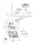
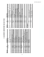
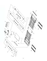
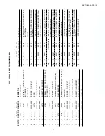
Page 29: ... BLOWER 7 1 44687 MOTOR BLOWER 208 230V 1 2HP 8 1 33983 HIGH LIMIT CONTROL MODULE 240V 9 1 36451 COOLINGFAN BACKWALL 10 1 97525 COOLINGFAN CONTROLCOMPARTMENT 11 1 50610 AIRSWITCH 12 1 48455 IGNITOR 13 1 50249 COMBINATIONGASCONTROLVALVE SAFETYREGULATOR 14 1 41647 MODULATINGGASVALVE M420 1 2 15 1 31651 AMPLIFIERBOARD 16 1 50239 IGNITIONMODULE 17 1 50240 IGNITION CABLE 25 SECTION5 PARTSLIST 1 2 3 4 5...

Page 30: ...24 ENGLISH ...

Page 31: ...SION FOR TRIPLE OVENS 5 2 2 2 22290 0009 CASTER WITH FLAT PLATE AND BRAKE 6 2 2 2 22290 0010 CASTER WITH FLAT PLATE NO BRAKE 7 1 1 1 21392 0004 EYEBOLT 3 4 8 31 31 31 220373 HEX BOLT 3 8 16 x 1 9 32 32 32 21416 0001 FLAT WASHER 3 8 10 32 32 32 21422 0001 LOCKWASHER 3 8 11 1 1 1 22450 0228 RESTRAINT CABLE ASSEMBLY 12 1 2 3 22361 0001 GAS HOSE 3 4 to 1 2 Gas hose reducer included with gas hose 13 1 ...

Page 32: ...26 ENGLISH page 1 FRANÇAIS page 57 ESPAÑOL página 85 DEUTSCH seite 29 ...

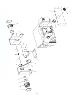
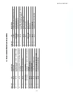
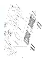
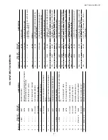
Page 33: ...92 HANDLE WINDOW 6 1 M1116 BRACKET RT WINDOW HANDLE 7 1 M1087 WLDMT GLASS FRAME WINDOW BG2136 8 1 57399 NAMEPLATE BLODGETT STAMPED 9 1 48687 DOOR MACHINERY COMPARTMENT FOR LEFT SIDE 10 1 48605 TOP PANEL 11 1 36451 COOLING FAN 12 1 47633 BACKWALL 13 1 31497 FINGER GUARD COOLING FAN 14 1 57388 DOOR CONTROL COMPARTMENT FOR RIGHT SIDE 15 8 48640 BRKT END PLUG MOUNTING 16 8 36452 WING NUT PLASTIC 17 2 ...

Page 34: ...28 ENGLISH page 1 FRANÇAIS page 57 ESPAÑOL página 85 DEUTSCH seite 29 ...

Page 35: ...V SEC 200VA 8 1 50610 SWITCH AIR 16 IN WC 9 1 35145 RESET SWITCH HIGH LIMIT 10 1 33983 HIGH LIMIT CONTROL MODULE 240V 11 2 44390 TERMINAL BLOCK 3 POLE 12 1 33813 RFI FILTER 13 1 97525 COOLING FAN 230V 14 1 37337 KIT CONVEYOR SPEED CONTROLLERPW DIGITAL DISPLAY INC ITEM 14A 14a 1 37503 DIGITAL DISPLAY ONLY 15 1 50990 CONTROL COMBO 4 20MA BURST 16 1 44696 SWITCH ROTARY MTG ADAPTOR 17 1 44697 BLOCK CO...

Page 36: ...30 ENGLISH page 1 FRANÇAIS page 57 ESPAÑOL página 85 DEUTSCH seite 29 ...

Page 37: ...GULATOR 11 1 41647 MODULATING GAS VALVE M420 1 2 12 A R 48740 TUBE ALUMINUM 1 4 6 35mm O D BULK 13 2 44888 COMPRESSION FITTING 1 4 TUBE 14 1 49940 MANIFOLD 15 2 30002 TAP PLUG ITEM QTY P N DESCRIPTION 16a 3 44984 ORIFICE MAIN NATURAL GAS 0 0935 2 3749mm 42 DRILL 16b 3 47320 ORIFICE MAIN PROPANE 0 0595 1 5113mm 53 DRILL 17 1 33812 1 KIT THERMOCOUPLE 18 1 48687 DOOR MACHINERY COMPARTMENT FOR LEFT SI...

Page 38: ...32 ENGLISH page 1 FRANÇAIS page 57 ESPAÑOL página 85 DEUTSCH seite 29 ...

Page 39: ...TH STANDARD GREASE 6 2 50160 GASKET BEARING 7 2 50151 BLOWER SHAFT 8 1 44748 COUPLING BLOWER SHAFT 9 1 44687 MOTOR BLOWER 208 230V 1 2HP 10 1 44688 PLATE MOTOR MOUNTING ITEM QTY P N DESCRIPTION 11 4 A11687 SCREW HEX CAP HEAD 5 16 18 X 7 8 12 4 B301A8847 FLAT WASHER 5 16 13 4 A3682 LOCK WASHER 5 16 14 1 50256 KIT RPM 50 60Hz CONTAINS SHEAVE 50260 WITH BUSHING 50259 15 1 50224 PULLEY BLOWER SHAFT 16...

Page 40: ...34 ENGLISH page 1 FRANÇAIS page 57 ESPAÑOL página 85 DEUTSCH seite 29 ...

Page 41: ...DLER SUPPORT 20 2 35000 1008 50028 SCREW IDLER ADJUSTMENT 21 2 35900 0398 PIVOT PLATE 22 4 21176 0002 LOCKNUT HEX 3 8 16 SS 23 1 51067 ASSEMBLY CONVEYOR MOTOR AND PICKUP INC ITEM 23a 23a 1 50163 PICKUP 24a 1 34128 SPROCKET CONVEYOR DRIVE MOTOR 20T STANDARD 25 1 22159 0003 SPROCKET CONVEYOR DRIVE SHAFT 20T 26 1 50050 50050 ASSEMBLY DRIVE CHAIN INC ITEM 26a 26a 1 3101212 MASTER LINK DRIVE CHAIN 27a ...

Page 42: ...36 ENGLISH page 1 FRANÇAIS page 57 ESPAÑOL página 85 DEUTSCH seite 29 ...

Page 43: ...R SUPPORT 20 2 35000 1008 50028 SCREW IDLER ADJUSTMENT 21 2 48755 PIVOT PLATE 22 4 21176 0002 LOCKNUT HEX 3 8 16 SS 23 2 51067 ASSEMBLY CONVEYOR MOTOR AND PICKUP INC ITEM 23a 23a 1 50163 PICKUP 24 2 34128 SPROCKET CONVEYOR DRIVE MOTOR 20T STANDARD 25 2 22159 0003 SPROCKET CONVEYOR DRIVE SHAFT 20T STANDARD AND HIGH SPEED 26 1 35900 0023 BUSHING DRIVE SPROCKET 27a 1 50050 50050 ASSEMBLY DRIVE CHAIN ...

Page 44: ...38 ENGLISH page 1 FRANÇAIS page 57 ESPAÑOL página 85 DEUTSCH seite 29 NOTES ...

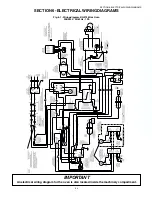
Page 45: ... 85 DEUTSCH seite 29 SECTION6 ELECTRICALWIRINGDIAGRAMS SECTION6 ELECTRICALWIRINGDIAGRAMS IMPORTANT An electrical wiring diagram for the oven is also located inside the machinery compartment Fig 6 1 Wiring diagram BG2136 Gas Oven 208 240V 50 60 Hz 1 Ph ...

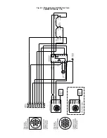
Page 46: ...Fig 6 2 Wiring diagram BG2136 Gas Oven 208 240V 50 60 Hz 1 Ph ...

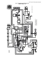
Page 47: ...SECTION6 ELECTRICALWIRINGDIAGRAMS Fig 6 3 Wiring diagram BG2136 Gas Oven 208 240V 50 60 Hz 1 Ph ...

Page 48: ...NOTES ...

Page 49: ...NOTES ...

Page 50: ...servicing this equipment NOTICE During the warranty period ALL parts replacement and servicing should be performed by your Blodgett Authorized Service Agent Service that is performed by parties other than yourBlodgettAuthorizedServiceAgentmayvoidyourwarranty NOTICE UsinganypartsotherthangenuineBlodgettfactorymanufacturedpartsrelievesthemanu facturerofallwarrantyandliability NOTICE Blodgett reserve...

Reviews: