


36
Configuration and adjustment variables
(1) Note:
• You cannot assign UPdt to Fr1 or Fr2 and UPdH to Fr1 or Fr2 at the same time. Only one of the UPdt/UPdH assignments is permitted
on each reference channel.
• The +/- speed function in Fr1 is incompatible with several functions (see page
). Before configuring it, these functions must be
unassigned, especially the summing inputs (set SA2 to nO page
) and the preset speeds (set PS2 and PS4 to nO page
) which are
assigned in the factory settings.
• In Fr2, the +/- speed function is compatible with the preset speeds, summing inputs and the PI regulator.
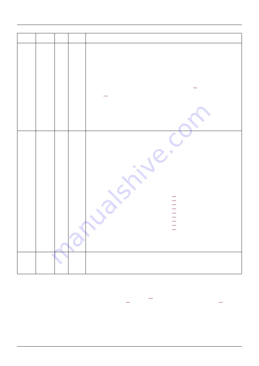
Modbus
address
CANopen
address
Code
Read/
Write
Name/Description/Possible values
8414
2036 / F
Fr2
R/WS
Configuration reference 2
Factory setting: 0
0 = "nO": Not assigned
1 = "AI1": Analog input AI1
2 = "AI2": Analog input AI2
3 = "AI3": Analog input AI3
16 = "AIV1": Potentiometer
If LAC = L2 or L3, the following additional assignments are possible:
160 = "UPdt": (1) + speed/- speed via LI. See configuration page
161 = "UpdH": (1) + speed/- speed using the jog dial. For operation, display the frequency rFr
(see page
). The +/- speed function via the jog dial is controlled from the SUP- menu by setting
to parameter rFr.
If LAC = L3, the following additional assignments are possible:
163 = "LCC": Reference via the remote display terminal, LFr parameter in the SEt- or SUP-
menu.
164 = "Mdb": Reference via Modbus
167 = "nEt": Reference via CANopen
8411
2036 / C
rFC
R/WS
Reference switching
Factory setting: 96
Parameter rFC can be used to select channel Fr1 or Fr2 or to configure a logic input or a control
bit for remote switching of Fr1 or Fr2.
96 = "Fr1": Reference = Reference 1
97 = "Fr2": Reference = Reference 2
129 = "LI1": Logic input LI1
130 = "LI2": Logic input LI2
131 = "LI3": Logic input LI3
132 = "LI4": Logic input LI4
133 = "LI5": Logic input LI5
134 = "LI6": Logic input LI6
If LAC = L3, the following additional assignments are possible:
187 = "C111": bit 11 of the CMD control word (page
) written by Modbus
188 = "C112": bit 12 of the CMD control word (page
) written by Modbus
189 = "C113": bit 13 of the CMD control word (page
) written by Modbus
190 = "C114": bit 14 of the CMD control word (page
) written by Modbus
191 = "C115": bit 15 of the CMD control word (page
) written by Modbus
203 = "C211": bit 11 of the CMD control word (page
) written by CANopen
205 = "C213": bit 13 of the CMD control word (page
) written by CANopen
206 = "C214": bit 14 of the CMD control word (page
) written by CANopen
207 = "C215": bit 15 of the CMD control word (page
) written by CANopen
The reference can be switched with the drive running.
Fr1 is active when the logic input or control word bit is at state 0.
Fr2 is active when the logic input or control word bit is at state 1.
8401
2036 / 2
CHCF R/WS
Mixed mode (control channels separated from reference channels)
Factory setting: 1
Active if LAC = L3
1 = "SIM": Combined
2 = "SEP": Separate


