180.SC30.NZ v1.01
December 4, 2017
Page 35
SC30L.NZ & SC30P.NZ
MAINTENANCE
BYPASS DOOR GASKET REPLACEMENT
BLAZE KING RECOMMENDS YOUR DEALER PERFORM THIS TASK
1. Will require THERMOSEAL® 1000SF high-temperature resistant
cement and Blaze King 5/8” dense fi ber glass gasket. See your Blaze
King dealer. You will also require masking tape and combustor gasket
as disassembly of the combustor will result in a damaged combustor
gasket.
2. Be sure the fi re is out and the stove has cooled down.
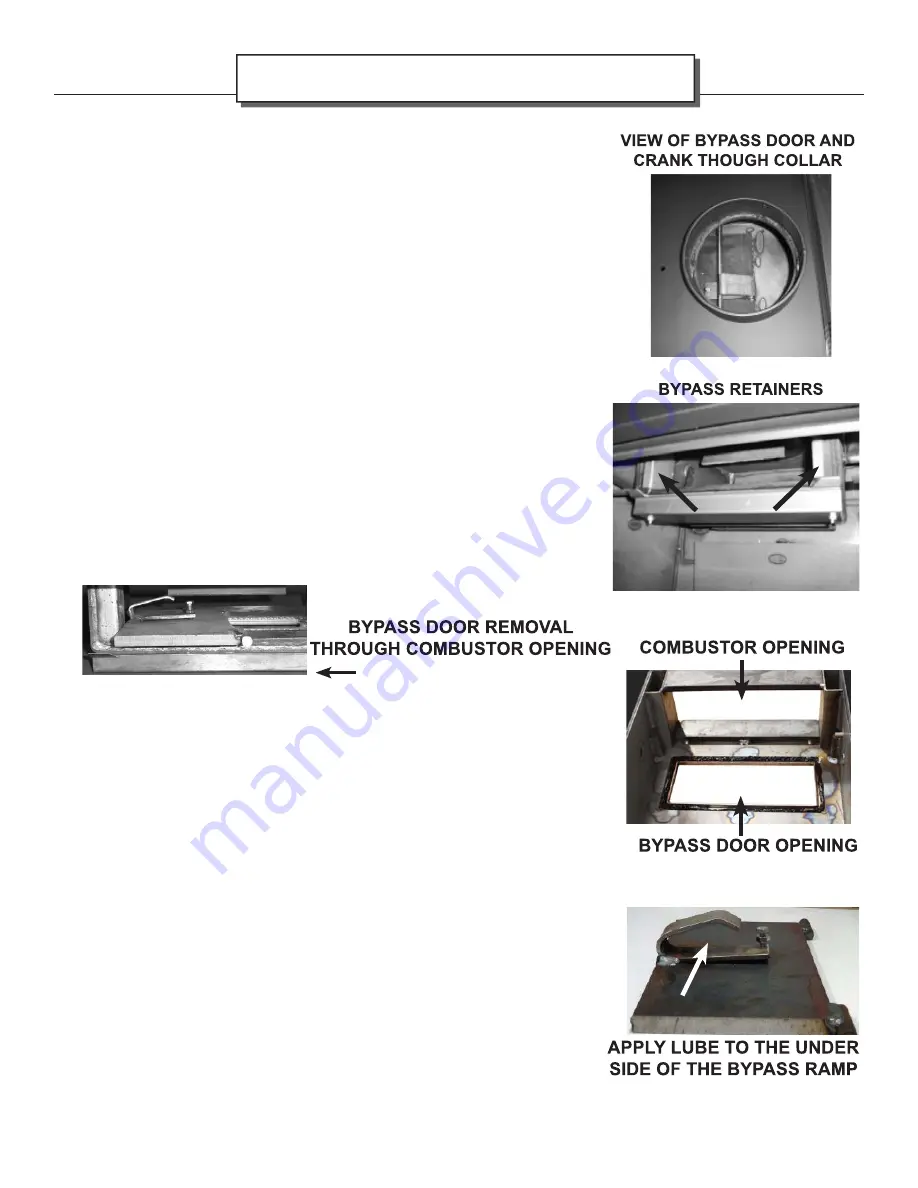
3. You will need to remove the liner from the collar of the stove, and have
the ability to see straight down into the stove box through the collar.
4. Please follow steps on “CATALYTIC COMBUSTOR, REPLACEMENT”
on how to remove your combustor.
5. After removing the combustor you will notice stainless bypass retainers
on the left and right sides of the combustor opening. These tabs prevent
the bypass door from popping out of its hinge holding pins during
operation. Remove the stainless bypass retainers by pulling inwards.
This will allow the bypass door to pop out of its hinge holding pins.
6. To remove the bypass door, move the bypass rod out of the way using
the bypass handle on the side of the stove. Looking down through the
collar, lift one end of the bypass door for clearance to turn inside the top
assembly. Once the bypass plate is in this position, remove the plate
through the combustor opening.
7. Remove the old gasket and
apply the THERMOSEAL® 1000SF high-temperature resistant cement
along the door opening edge.
8. Place the gasket along the cement, and tap it in to seat it securely in
the channel.
9. Replace bypass retainers.
10. Reverse method of removing bypass door to put it back in place.
11. Prior to reconnecting the liner, you will need to adjust the bypass ramp
bolt. You must fi rst loosen the retaining nut located under the head of
the adjustment bolt. Then using a 7/16” box wrench, tighten the bolt
until the bypass handle, when closed, has a slight cam-over feel. Do
not over tighten.
12. Secure bolt adjustment by tightening the 7/16” nut against the ramp as
seen in the photo to the left. Now work the bypass handle several times
to make certain the bypass operation is smooth and working properly.
When you are satisfi ed with the operation of the bypass, please lower
the venting. Important: Apply high temp anti-seize lubricant to the
under side of the bypass ramp where the rod contacts.
13. Please follow steps 5-8 on pages 30 & 31 to return the combustor into
place. Please note that if the gasket of the combustor is damaged, it
will have to be replaced.


