background image

SAFETY REQUIREMENTS

All user’s manual requirements as well as the provisions of all the applicable local and national 
construction, electrical, and technical norms and standards must be observed when installing 
and operating the unit.
Disconnect the unit from power supply prior to any connection, servicing, maintenance, and 
repair operations. 

Only  qualified electricians with a work permit for electrical units up to 1000 V are 

allowed for installation and maintenance. The present user’s manual should be carefully 

read before beginning works.

•  Single-phase power mains must comply with the acting local electrical norms and standards. 
•  Fixed electrical wiring must be equipped with an automatic circuit breaker.
•  The unit must be connected to power mains through a double pole circuit breaker of suitable 

rating integrated into the fixed wiring system with opening of contacts at all poles.  The gap 
between the circuit breaker contacts at all poles must be not less than 3 mm. 

•  If the supply cord is damaged, it must be replaced by a special cord or assembly available 

from the manufacturer or its service agent.

•  Check the unit for any visible damage of the impeller, the casing, and the grille before starting 

installation. The casing internals must be free of any foreign objects that can damage the 
impeller blades. 

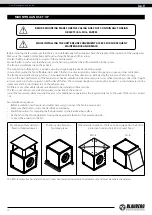
•  While mounting the unit, avoid compression of the casing! Deformation of the casing may 

result in motor jam and excessive noise.

•  Misuse of the unit and any unauthorized modifications are not allowed.
•  Do not expose the device to adverse atmospheric agents (rain, sun, etc.).
•  Take steps to prevent ingress of smoke, carbon monoxide, and other combustion products 

into the room through open chimney flues or other fire-protection devices. Sufficient air 
supply must be provided for proper combustion and exhaust of gases through the chimney 
of fuel burning equipment to prevent back drafting.

•  Transported air must not contain any dust or other solid impurities, sticky substances, or 

fibrous materials.

•  Do not use the unit in a hazardous or explosive environment containing spirits, gasoline, 

insecticides, etc.

•  For effective functioning of the unit, it is necessary to ensure an appropriate fresh air supply 

into the room. Do not close or block the intake or extract vents in order to ensure the efficient 
air flow.

•  Do not sit on the unit and do not put objects on it.
•  The unit is allowed to be used by children aged from 8 years old and above and persons with 

reduced physical, sensory, or mental capabilities or no experience and knowledge provided 
that they have been given supervision or instruction regarding safe use of the unit and 
understand the risks involved. 

•  Do not allow children to play with the unit. 
•  Cleaning  and  user  maintenance shall not be made by children without supervision.
•  The information in this user’s manual was correct at the time of the document’s preparation. 

www.blaubergventilatoren.de

iso-V

3

Summary of Contents for Iso-V

Page 1: ...Duct centrifugal fan in sound insulated casing USER S MANUAL EN Iso V Iso V EC ...

Page 2: ...he right to modify the technical characteristics design or configuration of its products at any time in order to incorporate the latest technological developments No part of this publication may be reproduced stored in a retrieval system or transmitted in any form or by any means in any information search system or translated into any language in any form without the prior written permission of th...

Page 3: ...the casing Deformation of the casing may result in motor jam and excessive noise Misuse of the unit and any unauthorized modifications are not allowed Do not expose the device to adverse atmospheric agents rain sun etc Take steps to prevent ingress of smoke carbon monoxide and other combustion products into the room through open chimney flues or other fire protection devices Sufficient air supply ...

Page 4: ...ents No part of this publication may be reproduced stored in a retrieval system or transmitted in any form or by any means in any information search system or translated into any language in any form without the prior written permission of the Company WARNING Similar to the use of any other household electrical appliances when operating this fan the following basic rules must be followed Never tou...

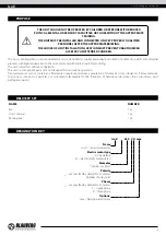
Page 5: ...d for continuous operation The unit is a component part and is not designed for stand alone operation Transported air must not contain any flammable or explosive mixtures evaporation of chemicals sticky substances fibrous materials coarse dust soot and oil particles or environments favourable for the formation of hazardous substances toxic substances dust pathogenic germs NAME NUMBER Fan 1 pc User...

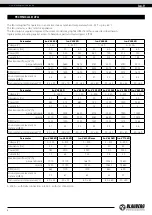
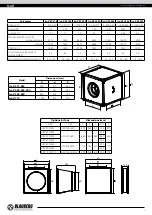
Page 6: ...50 4E Iso V 450 4D Iso V 500 4E Iso V 500 4D Iso V 560 4D Voltage V 3 400 Y 1 230 3 400 1 230 3 400 3 400 Frequency Hz 50 60 50 50 50 50 50 Power W 385 515 680 740 1300 1430 2380 Current A 0 7 0 93 3 1 5 5 7 3 5 Maximum air flow m3 h perpendicularly 3340 3525 5630 5700 7330 7940 11340 directly 3110 3290 4930 5080 6680 7200 10490 RPM min 1 1235 1220 1250 1350 1320 1375 1365 Sound pressure level at ...

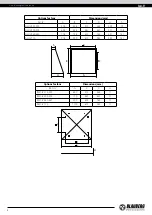
Page 7: ... 1300 Sound pressure level at 3 m distance dBA 35 44 39 50 45 50 50 Transported air temperature С 40 80 25 60 25 50 25 60 20 50 25 60 25 55 Model Dimensions mm H A B Iso V 315 355 500 310 460 Iso V 400 450 500 670 480 630 Iso V 560 630 800 610 760 Iso V 710 1000 810 960 H A A H B B Options for fans Dimensions mm ARV AKV A B C ØD F ARV 500 355 AKV 500х500 490 460 310 354 470 ARV 670 400 AKV 670х670...

Page 8: ...8 480 630 321 108 AH IV 560 630 778 758 610 760 421 141 AH IV 710 978 959 810 960 422 141 D h H A B C Options for fans Dimensions mm RSD IV A C D H RSD IV 315 355 600 310 460 11 RSD IV 400 500 770 480 630 11 RSD IV 560 630 900 610 760 11 RSD IV 710 1100 810 960 11 A D C H www blaubergventilatoren de Iso V 8 ...

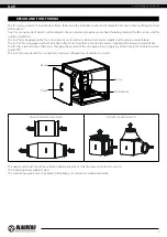
Page 9: ...with an external rotor and an impeller with backward curved blades The fan has a special design that allows changing the position of the side panels for air supply in all directions both linearly and at an angle of 90 The Iso V fans may be used for construction of various configurations of ventilation systems Motor Frame Panel Terminal box Linear connection of air ducts Air duct connection at 90 T...

Page 10: ...3 air duct diameters on the exhaust side No filters or any other similar devices are allowed to be installed in these sections The fan is not a ready to use unit and requires connection to the air ducts Install the fan securely while ensuring free access for maintenance operations the required distance to the walls of the room is at least 1 m Fan installation sequence Before installation lay the w...

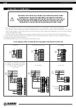
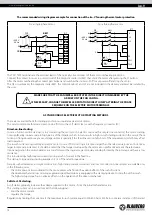
Page 11: ...W1 TW2 TW1 TW2 РЕ L N X1 N L QF PE 230 V Hz 50 РЕ L2 L1 QF PE 400V Hz 50 L2 L1 L3 L3 L1 L2 L3 РЕ Подключение аналогового выхода 0 10 V прибора управления 0 10 V GND KL3 Подключение релейного выхода прибора управления 0 10 V 10 V KL3 KL3 Подключение регулятора потенциометра 0 10 V GND 10 V Подключение датчика критического давления 4 20 4 20 mA 20 V KL3 X1 X1 QF KM1 KM1 L1 KM1 QF L1 L N X1 1 2 3 N L...

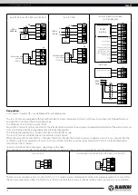
Page 12: ... range The efficiency of such motors reaches 90 Fans with EC motors must be connected to the terminal block located in the external or integrated terminal box of the electric motor in strict accordance with the wiring diagram and terminal designation The terminal designations are shown on the label inside the fan casing The Iso V EC fans are controlled via various external control signals When the...

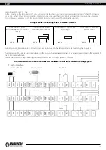
Page 13: ... TW2 PE L2 L2 L1 2 7 3 L3 L3 5 4 6 V1 U1 PE U2 8 9 РЕ Подключение аналогового выхода 0 10 V прибора управления 0 10 V GND KL3 Подключение релейного выхода прибора управления 0 10 V 10 V KL3 KL3 Подключение регулятора потенциометра 0 10 V GND 10 V Подключение датчика критического давления 4 20 mA 4 20 mA 20 V KL3 L N X1 X1 1 2 3 L QF N PE TW1 4 5 6 TW2 230 V Hz 50 KM1 S1 ON S2 OFF KM1 РЕ L1 TW1 TW2...

Page 14: ... the feed line section falls short of the requirements which may affect load operation The in rush current consumed by an electric motor in case of DOL starting is 5 8 times larger than the rated value or even 10 14 times larger in some rare instances It should be noted that the torque developed by the motor also significantly exceeds the rated value Upon energisation the motor operates as a trans...

Page 15: ...nt Typical symptoms Upon starting the circuit breakers at the system input are tripped the lights certain relays and contactors go off and the supply generator shuts down Solution In the best case scenario an SS device may help reduce the in rush current to 250 of the motor rated current If this is insufficient an FC is necessary 2 The motor cannot start the mechanism with DOL starting Typical sym...

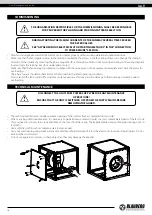
Page 16: ...ing or insulation due to overheating DURING STARTING THE IN RUSH CURRENTS OF THE FAN MAY SEVERAL TIMES EXCEED THE RATED VALUES SEE ASYNCHRONOUS ELECTRIC MOTOR STARTING METHODS IN THE CONNECTION TO POWER MAINS SECTION TECHNICAL MAINTENANCE DISCONNECT THE UNIT FROM POWER SUPPLY BEFORE ANY MAINTENANCE OPERATIONS ENSURE THAT THE UNIT IS SWITCHED OFF FROM THE SUPPLY MAINS BEFORE REMOVING THE GUARD The ...

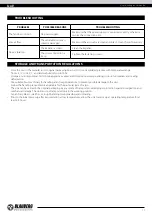
Page 17: ...per protection against precipitation and mechanical damage The unit must be transported only in the working position Avoid sharp blows scratches or rough handling during loading and unloading Prior to the initial power up after transportation at low temperatures allow the unit to warm up at operating temperature for at least 3 4 hours TROUBLESHOOTING PROBLEM POSSIBLE REASONS TROUBLESHOOTING The fa...

Page 18: ...ufacturer s warranty does not apply to the following cases User s failure to submit the unit with the entire delivery package as stated in the user s manual including submission with missing component parts previously dismounted by the user Mismatch of the unit model and the brand name with the information stated on the unit packaging and in the user s manual User s failure to ensure timely techni...

Page 19: ...__ unit is installed pursuant to the requirements stated in the present user s manual Installation Stamp Company name Address Phone Number Installation Technician s Full Name Installation Date Signature The unit has been installed in accordance with the provisions of all the applicable local and national construction electrical and technical codes and standards The unit operates normally as intend...

Page 20: ...www blaubergventilatoren de B19EN 05 ...

Reviews: