


www.blaubergventilatoren.de
iSO-rB eC
6
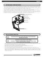
Cover
Terminal box
Sound-insulated casing
Motor impeller
Electric lead-ins
Mounting brackets
Transported air flow direction
The fan casing is made of aluzinc. For easy installation and operation, the top cover of the fan is secured with a special lock. The casing
is heat- and sound-insulated with a 50 mm layer of non-flammable mineral wool. To ensure better noise absorption, the inner surface of
the insulation is made of a perforated metal sheet. The round connecting spigots are rubber sealed.
The fan is equipped with an electronically commutated motor with an external rotor and an impeller with backward curved blades. The
low-noise motor with ball bearings with specially selected grease ensures maintenance-free operation of the fan.
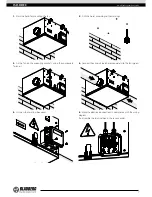
Duct fans are intended for mounting to round air ducts. The fans are installed between the air ducts. In case the fan is mounted on
flexible joints, attach the fan to a structural unit by means of supports, suspension links or brackets (purchased separately). The fan may
be installed in any position in consideration of the air flow direction (as indicated by the arrow on the fan casing).
UNIT DESIGN AND OPERATING PRINCIPLE
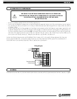
INSTALLATION AND CONNECTION
WHILE INSTALLING THE UNIT ENSURE CONVENIENT ACCESS FOR SUBSEQUENT
MAINTENANCE AND REPAIR.
THE UNIT MUST BE MOUNTED ON A PLANE SURFACE.
MOUNTING OF THE UNIT TO AN UNEVEN SURFACE CAN LEAD TO THE UNIT CASING
DISTORTION AND OPERATION DISTURBANCE.
• Before installing the fan, make sure the casing has no visible damages and check the integrity of power supply wires. The fan casing
must not contain any foreign objects which can damage the impeller blades.
• Make sure the impeller rotates freely without touching the flange and the casing.
• Mount the fan in such a way that the arrow on the fan casing matches the air flow direction in the system.
• The casing has mounting brackets to facilitate the fan installation.
• The fan may be installed in any position in consideration of the air flow direction (as indicated by the arrow on the fan casing).
• To attain the best performance of the fan and to minimize turbulence-induced air pressure losses while mounting, connect the
straight air duct section to the fan spigots on both sides of the fan. The minimum straight air duct length is equal to 1 air duct
diameter on the intake side and 3 air duct diameters on the exhaust side. No filters or any other similar devices are allowed to be
installed in these sections.