


DRP 393 MPEG-4 Receiver/Decoder
Rev. L
www.blankom-digital.de
Page 5 (36)
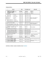
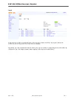
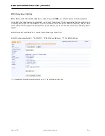
Input
Different DVB Input Frontends can be implemented. HF input variants are 75 Ohm F-port or 50 Ohm SMA-
port.
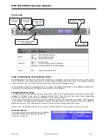
ASI interface
There are 2 equivalent ASI outputs on the back side of the device. There is 1 ASI test output on the device
front panel. If a fault occurs, the ASI operating outputs can be switched off. The test output cannot be
switched off. Depending upon the (software) configuration and option, the originally received TS or the TS
with one or more descrambled services can be maintained on the ASI outputs. As a standard, an ASI input is
provided for on the back side of the device. If an additional frontend is implemented, it is possible to switch
over between the ASI and Frontend input.
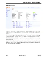
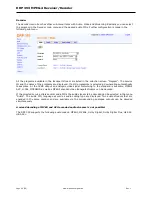
MPEG-4 video decoder
The decoder supports MPEG-4 part10 (AVC, H.264) as well as MPEG-2 decoding. During an anamorphous
16:9 video transmission, the decoder generates a Letterbox video format from this signal. Moreover, the
decoder can generate a SDTV signal (720x576) in the Letterbox format from the HDTV signal (1920x1080i,
1280x720p) by “downscaling”. This decoder also supports DVB subtitling. The output signal is the analogue
CVBS signal.
DRP 393 supports extensive VBI functionalities: The teletext lines, the data lines and the WSS signal as well
as the test lines are entered in the analogue output signal.
All the 13 data bytes are transferred to the VPS data line (line 16). The audio status is generated according
to the selected audio output format (basis: Audio output 1). The CNI code can be manually entered if it is
not available within the TS (Transport stream).
The test lines 17, 18, 330, 331 and 329 are generated within the device. Line 331 can be assigned the CCIR
or ramp signal. Line 329 can be assigned the sinx/x signal, teletext or data line.
The WSS signal (line 23) is generated according to the aspect ratio of the video output signal. If the
letterbox conversion leads to a disturbing stream like a “string of beads” in the enabled video signal, this can
be suppressed with the WSS letterbox muting function (blanking / suppression of line 59).
A colour bar test signal can be enabled for the purpose of testing.
2
nd
Video output
Optionally a 2
nd
video output is available. This output cannot be simultaneously integrated in the device with
the HD-/SD-SDI option.
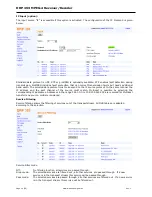
HD-SDI/SDI output
The HD-/SD-SDI output is an optional setting / configuration for DRP 393. It is designed as an additional
plug-in module. This option supports SD-SDI with a data rate of 270 Mbpsas well as HD-SDI with a data rate
of 1.485 Gbps. Up to 4 additional audio channels can be embedded in the SDI signal. Besides, a separate
output is available AES/EBU audio signal.
Audio decoder
The basic device has 4 audio output channels (2 stereo / dual-tone). Two audio PIDs can be decoded within
the device. Thus, the audio track for blind persons (e.g. ZDF) and the dual tone can be generated from two
stereo PIDs (e.g. Arte). The level of every audio output can be set individually.
Dolby Digital is decoded and given out as a stereo signal.
Optionally, 4 other audio output channels can be activated.
Note: Dolby Digital (AC3) and MPEG audio signals cannot be decoded simultaneously!
For test purpose, 1 kHz test signal, nominal level +6 dBm can be enabled. The test signal is available on all
audio outputs.
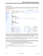
Digital audio output SPDIF
The PID selected for audio decoder 1 can also be given out via the digital SPDIF output. If a Dolby Digital
signal (AC3) is selected, the AC3 signal (which is not decoded) can also be given out (“pass thru”).


