


2
8
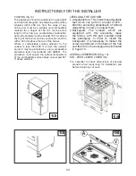
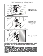
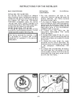
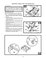
INSTRUCTIONS FOR THE INSTALLER
ELECTRICAL CONNECTION
The appliance is supplied with a 15A power plug
fitted to the supply cord. Connect the plug to
a 15A General Purpose Outlet (GPO) which is
properly earthed and installed by an authorised
electrician. If a 15A GPO is not available then an
authorised electrician must install the appliance
as follows:
FIXED WIRING.
The electrical connection must be carried out
in accordance with the current standards and
laws in force and by an authorised electrician.
• W
arning this appliance must be earthed.
•
Connection to the electricity supply must
be made by an authorised electrician to a
suitable isolating switch in accordance with
the requirements of SAA Wiring Rules, AS/NZS
3000.
•
A H05 RR-F 3x1.5 mm2 cable must be used.
•
Means of disconnection shall be provided in the
fixed wiring in accordance with the Australian
wiring rules.
•
Remember that the earth wire must be longer
than the phase wires.
•
Note: The power supply cable must be
positioned so that no part of cable can come
into contact with any surface which could
reach temperatures in excess of 75 K.
•
If the supply cord is damaged, it must be
replaced by the manufacturer, its service agent
or similarly qualified persons in order to avoid
a hazard.
ADJUSTMENTS
•
Always disconnect the appliance from
the electricity supply before making any
adjustment.
•
All seals must be replaced by the technician
following any adjustment or regulation.
•
The adjustment of the reduce rate (simmer)
must be undertaken only with burners
functioning on natural gas while in the case
of burners functioning on Propane, the screw
must be locked down fully (in clockwise
direction).
•
“Primary air adjustment” on hob gas burners
is unnecessary.
•
If the appliance cannot be adjusted to
perform correctly refer to the authorised
service provider in your area.
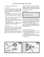
TAPS (fig. 19)
All gas taps are male cone type with only one way
of passage. The adjustment screw (V) is on the
side of the stem.
Adjustment of the “Reduced rate” position as
follows:
19
l• Turn the burner on and place the knob on the
“reduced rate” position (small flame).
• remove the knob of the tap which is attached
by simply applying pressure to the rod.
• With a small screwdriver (C) turn to the right or
left the adjustment screw (v) until the flame of
the burner is conveniently regulated to the Low
position.
• Check that the flame does not go out when the
knob is sharply switched from the “Full on” to
“Reduced rate” positions.
Hot Plate Ignition Failure
• Check alignment of burner holes to electrode.
• Check aeration sleeve for adjustment for gas
type, location and ambient conditions.
• No spark, check ignition box failure or power
supply.
Before Leaving
• Check all connections for gas leaks with soap
and water. DO NOT
use a naked flame for
detecting leaks. Ignite all burners to ensure
correct operation of gas valves, burners and
ignition.
• Turn gas taps to low flame position and observe
stability of the flame. When satisfied with the
cooker, please instruct the user on the correct
method of operation.
• In case the appliance fails to operate correctly
after all checks have been carried out, refer to
the authorised service provider in your area.
CHANGING THE FLEXIBLE GAS HOSE
In order to guarantee that the gas hose is always
in excellent condition we strongly recommend
changing it on the date you will find printed on it.
Summary of Contents for BFD9054WX
Page 1: ...Instruction Manual for BLANCO 90cm Freestanding Cooker BFD9054WX 461308250_001 10 2013 ...
Page 10: ...10 ...
Page 32: ...32 TECHNICAL FEATURES WIRING DIAGRAM COOKER BFD9054WX ...
Page 33: ...33 We appreciate your feedback Please review our products on www blanco australia com ...
Page 34: ...34 ...
Page 36: ......


